
actuators
Review
Recent Advances in Design and Actuation of
Continuum Robots for Medical Applications
Yong Zhong * , Luohua Hu and Yinsheng Xu
Shien-Ming Wu School of Intelligent Engineering, South China University of Technology,
Guangzhou 511442, China; [email protected] (L.H.); [email protected] (Y.X.)
* Correspondence: [email protected]
Received: 20 October 2020; Accepted: 15 December 2020; Published: 19 December 2020
Abstract:
Traditional rigid robot application in the medical field is limited due to the limited
degrees of freedom caused by their material and structure. Inspired by trunk, tentacles, and snakes,
continuum robot (CR) could traverse confined space, manipulate objects in complex environment,
and conform to curvilinear paths in space. The continuum robot has broad prospect in surgery
due to its high dexterity, which can reach circuitous areas of the body and perform precision
surgery. Recently, many efforts have been done by researchers to improve the design and actuation
methods of continuum robots. Several continuum robots have been applied in clinic surgical
interventions and demonstrated superiorities to conventional rigid-link robots. In this paper,
we provide an overview of the current development of continuum robots, including the design
principles, actuation methods, application prospect, limitations, and challenge. And we also provide
perspective for the future development. We hope that with the development of material science,
Engineering ethics, and manufacture technology, new methods can be applied to manufacture
continuum robots for specific surgical procedures.
Keywords: continuum robots; design principles; actuation methods; future challenges
1. Introduction
1.1. Background
With the maturity of robot technology, the application of robots is gradually penetrating from
the manufacturing industry to all aspects [
1
,
2
]. Traditional rigid robots have shown broad prospect
in service industry, real estate industry, agriculture and other aspects. In recent years, robots have
gradually shown their potential in the medical industry [
3
]. Medical robots have brought a new
breakthrough for the realization of surgery. However, traditional rigid robots cannot meet the
requirements of more precise surgical accuracy due to the limitation of flexibility due to their rigid
structure [
4
]. Especially when performing the operation of the internal position of the human body,
the disadvantages of the rigid robot are particularly obvious. The rigid robot cannot match the
flexibility of the human organs, and it is difficult to access the circuitous parts of the human body.
The emergence of flexible robots provides a solution of this problem. Flexible robots can be segmented
into two categories, including finite-degree-of-freedom robots that are linked by a limited number of
discrete joints and infinite-degree-of-freedom robots without joint links showed as elastic members [
5
].
The infinite-degree-freedom (infinite-DOF) robots is also called continuum robots (CRs). It was first
proposed in the 1960s [
6
,
7
]. Because of its flexibility in movement brought by the infinite degrees of
freedom, researchers have paid increasing attention to it. Many ideas of bio-inspired CRs have been
proposed, and the review of continuum robots applied in the medical field has also appeared [7,8].
Actuators 2020, 9, 142; doi:10.3390/act9040142 www.mdpi.com/journal/actuators
Actuators 2020, 9, 142 2 of 30
1.2. Outline
Research on CRs usually involves four aspects—design, actuation, modeling, and control.
Inspiration and design are the basis for the development of a robot. CRs are a new kind of robot.
Many design principles are essentially different from existing robots [
9
,
10
]. Traditional robots
emphasize accuracy. Due to their inherent rigid structure, their flexibility is poor which limits their
application in many occasions. As a kind of flexible robot, the CRs focus on the human body and other
occasions, and pays more attention to the interaction between the robot and the human. So its design
principles emphasize flexibility and bionics. The actuation of the robot is the basis for realizing all the
functions of the robot. This paper reviews the design and actuation of CRs based on the latest research
results of CRs. Section 2 describes the design principles, structural features and methods of variable
stiffness of the CRs. Section 3 introduces the actuation methods of the CRs. Section 4 introduces the
application of CRs and the challenges in research.
2. Continuum Robots Inspiration and Design
Traditional rigid robots are generally used in a variety of fields. But because of the lack of
flexibility, they are not suitable for working in environment with many constraints and very complex
terrain, which requires high degree of freedom, especially in the medical field. We thus introduce a
new type of bio-inspired robot with high flexibility, which is called CR. Compared with traditional
rigid robots, CRs mimic this unique invertebrate of biological organs such as elephant trunk and
octopus tentacles [
11
]. The structure, with higher security and flexibility, can flexibly change its shape
to suit different environment, and has its unique advantages in this highly demanding work.
In this section, the bioinspired principles of CRs will be described. Then, the structural design
and characteristics of CR will be discussed. Finally, the latest variable-stiffness methods of CRs will
be listed.
2.1. Bio-Inspired Principles
Bionics is both an ancient and a young subject. People study the principle of the structure
and function of living organisms, and based on their principles to invent new equipment, tools and
technology to bring welfare for mankind. CR is a novel type of bio-inspired robot, which imitates the
motion mechanism of animal organs such as elephant trunk and octopus arm in nature. It does not have
motion joints, but could realize movement and grasping operations by continuous flexible deformation.
It is the biological structure which has an enormous capacity for extending quickly and bend in
various kinds of direction, and can change its own stiffness according to needs, which is convenient
for operation. Smith et al. first published articles on the movement mechanism of elephant trunk [
12
].
Rice University started to research and develop elephant-like robot, and many research institutions
and scholars later joined in this field [
13
]. Margheri L et al. [
14
,
15
] analyzed the octopus arm from the
perspective of biomorphology and obtained relevant data for the design of soft octopus robot [
16
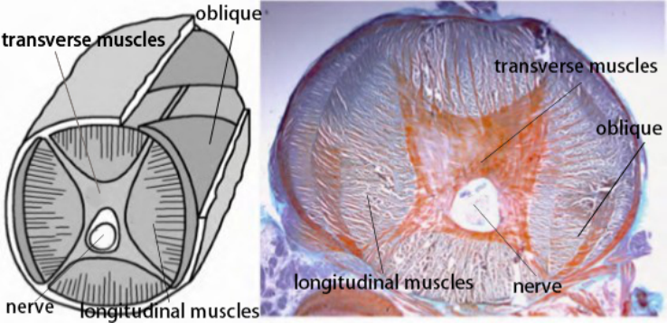
]. As is
shown in Figure 1, the muscular structure of the octopus arm is made up of transverse, longitudinal and
oblique muscles. L, T, O and N are transverse muscles, longitudinal muscles, oblique muscles and nerve.
Transverse muscle contractions cause octopus arms to elongate. Longitudinal muscle contraction
leads to thickening of octopus arms. Simultaneous contraction of lateral and partial longitudinal
muscles will lead to flexion of octopus arms. The distortion of the arm is caused by contraction of the
oblique muscle [
17
]. CRs have applications (Bio-Inspired) in all walks of life, for example, medical,
industry, rescue, hazardous place, space, underwater and military. This paper mainly focuses on
medical examples.
Actuators 2020, 9, 142 3 of 30
Figure 1. Muscle structure of octopus arm [18].
2.2. Structural Design and Characteristics
According to the actuation mode, there are three typical bio-inspired design schemes for
continuum robots [
19
]: (1) Intrinsic Actuation, (2) Extrinsic Actuation, (3) Hybrid Actuation.
Burgner-Kahrs et al. [
20
] pointed out that CRs can be classified not only on the basis of their
structural design but also actuation strategy. They divided CRs with elastic structure into intrinsic
actuation, which include concentric tube, tendon/cable and multi-backbone, and extrinsic actuation,
which include pneumatic, hydraulic and shape memory. CR has the following advantages [
21
]:
(1) It can bend freely and its bending radius is small; (2) Its external size can be small and it can
move in narrow workspace such as pipelines; (3) Its adaptability to non-structural environment with
multiple obstacles is strong; (4) In addition to the end can be installed with an actuator to complete the
operation, the whole robot body can also serve as an actuator to grasp the target. The disadvantages of
continuums robot are as follows: (1) It is difficult to control multi-degree-of-freedom bending; (2) Most
CR’s control accuracy is not high; (3) Due to the limitation of robot structure, its load capacity is not high.
Srikanth et al. [
22
] divided the continuum models into the following categories: Single segment [
23
–
25
],
Multisegment [
26
–
28
], Single segment-multidisc [
29
–
31
], Multi segment-multidisc [
32
–
34
] and
Continuous structure [
35
–
37
]. Among them, the body of single segment continuum robots consists
of a single backbone-like structure with limited constant curvature freedom of motion. They have
the advantage of being simple in structure and are often used for cleaning. Their driving systems are
diverse, including pneumatic, magnetic actuation, and so forth. The body of multi-segment continuum
robots consists of multiple segments, each with the freedom to move as a single element structure,
but independent of other elements. Its advantage is connection control, often used for Inspection.
Their driving systems are diverse, including pneumatic, tendon-cable driven, and so forth.
In this subsection, the recent common structures are selected for discussion.
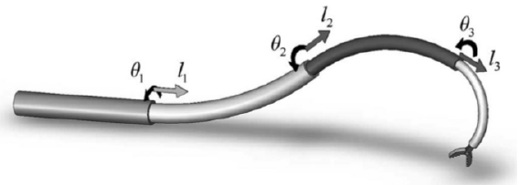
2.2.1. Concentric Tube Continuum Robots
The concentric-tube robots are made up of a number of pre-curved elastic tubes, which are nested
within each other. The shape of the robot structure can be controlled by the axial translation and
rotation of the base of each tube. The reason why each tube can be processed into the desired shape by
heat treatment prior to assembly is that these tubes are generally made from the shape memory alloy
NiTi at the superelastic stage [
20
]. As is shown in Figure 2, because of its light weight and slender
features, the concentric tube robots can come true the curve of complex shape only by rotating and
translating the concentric tubes relatively [
38
]. As a surgical device for minimally invasive surgery,
concentric robot is considered to have a great prospect because the tip position and direction of the
concentric robot can be guided and controlled directly along the specified paths.
Actuators 2020, 9, 142 4 of 30
Figure 2. Concentric tube robot consisting of four tubes [38].
For example, to meet the constraints of anatomy, surgical tasks, and leader-following deployment,
Xing Yang et al. [
39
] proposed a design and optimization method for a patient-specific concentric tube
robot, which is abbreviated CTR. CTR is a kind of tentacle-like CR that can operate in a closed complex
biological cavity and has the ability to track complex three-dimensional trajectories. To accommodate
the surgical tools, the structure consists of a pre-curved superplastic tubes and some hollow cavities.
2.2.2. Tendon/Cable Continuum Robots
Tendon/Cable-driven CRs are to arrange the cables along the axis direction of the mechanical
arm. By pulling the cables, the mechanical arm is driven to bend or twist. Zhou et al. [
40
] proposed a
new configuration of a 6-DOF tendon-driven CR for single-port surgery. The deformable skeleton of
the robot is made from the super-elastic nickel-titanium materials and manufactured by integrated
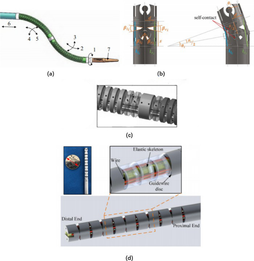
processing technology, and has a series of elastic joints with cross-cut notches. As is shown in Figure 3a,
the overall structure of the manipulator arm designed for single-hole surgery is largely made up
of basic structures such as the proximal supporting straight rod segment, 2-segment continuum
structure segment, rotating wrist joint and front-end actuator. To favourably achieve the customized
constant/nonconstant curvature, Anzhu et al. [
41
] proposed a contact-aided laser-profiled CR with
series interlocking joints. The Figure 3b shows one part of the cable-driven CR with contact-aided
compliant mechanisms. This structure minimizes collisions with the bronchi.
Aiming at low positioning accuracy and difficulty in entering the natural cavity or minimally
invasive incision of traditional surgical instruments, Zhao et al. [
42
] designed a line-driven continuum
surgical robot system. The composition of the system include UR robot arm, Stewart parallel
platform, the continuum end effector and force feedback handle. Gao et al. [
43
] presented wire-driven
multi-segment robot based on push-pull wires. This robot has been tested to attain follow-the-leader
(FTL) motion, placing surgical instruments through narrow passages while minimizing the trauma
to tissues. Figure 3c shows three-dimensional computer-aided design model of this kind of CR.
Wang et al. [
44
] proposed a new notch continuum manipulator (CM) for laryngeal surgery, consisting
of guide-wire discs and a Nitinol skeleton. The Figure 3d shows the model of the CM. The tendon/cable
actuation is easy to realize and relatively simple to control [
45
]. It can transfer the driving force over a
long distance to ensure a small moment of inertia of the mechanical arm.
However, there are some problems: tendon/cable actuation generally requires an electric motor
and a transmission mechanism, so the system is relatively bulky [
17
]. In the next chapter of this paper,
tendon/cable driven will be discussed in detail.
2.2.3. Origami Continuum Robots
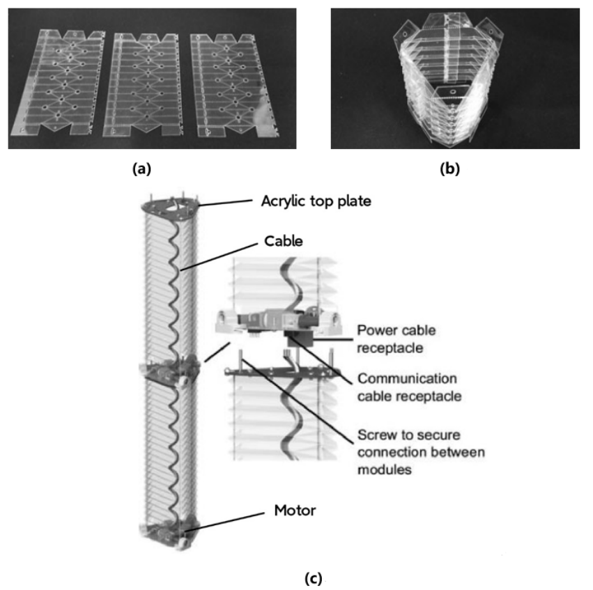
Origami is a traditional art, but in recent years, researchers have gained a lot of new inspiration
from origami. The process of origami is very similar to that of a continuum robot. At the
same time, the telescopic details of the robot can be designed based on the layout of the creases.
Common creases are Miura pattern, water bomb pattern, Yoshimura pattern and diagonal pattern.
Junius Santoso et al. [
46
] designed a continuum robot based on the origami structure (shown in
Figure 4), which can achieve 73 times the torque output and 1.25 times the length change of the
Actuators 2020, 9, 142 5 of 30
same-body robot. Its substrate material is PET sheet, due to the high strength-to-weight ratio and
ready availability. Each origami continuum robot consists of two modules. Each module consist
of a compliant plastic body, an acrylic end plate, and a custom-made PCB for embedded control.
The driving force of the motor consists of 4 wires passing through the origami space. The wires of
the cavity are transferred to the origami structure, and the origami force is provided by the inherent
bending stiffness of the origami structure. Compared with other continuous robots, the origami robot
does not have a rigid or flexible skeleton, and only the origami crease can provide restoring force.
This makes it possible to design the system to be lighter because it eliminates equipment such as
springs and magnets. In addition, the modular nature of the proposed origami structure allows the
entire system to be scaled if necessary.
Figure 3.
(
a
) The demonstration of structure and degree-of-freedom (DOF) [
40
]; (
b
) A segment of the
cable-driven continuum robot (CR) with contact-aided compliant mechanisms [
41
]; (
c
) 3D model of the
wire-driven CR [43]; (d) One segment of the CM [44].
2.2.4. Magnetic Continuum Robots
Since the magnetic CR consists of uniform soft polymer matrix and uniformly dispersed
magnetic particles, the robot can not only be miniaturized in diameter, but its hydrogel skin can
Actuators 2020, 9, 142 6 of 30
also reduce friction. Lloyd et al. [
47
] presented a elongated, soft, magnetic-driven, tentacle-shaped
robot and proposed a new design method derived from Neural Network (NN) trained using
Finite Element Simulations (FES). They demonstrated how their design method produces static
and homogeneous-driven 2D tentacle contour under the deformations derived from predefinition
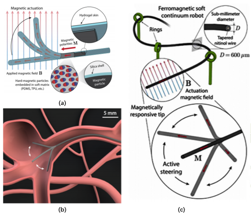
and expectation. Yoonho Kim et al. [
48
] proposed a soft CR that is not only submillimeter in size
but also self-lubricating. The abbreviation of this robot is SFSCR, it means submillimeter-scale
ferromagnetic soft continuum robot. By programming the ferromagnetic domains on soft body
while the hydrogel skin grows on its surface, SFSCR has a strong magnetic-driven omnidirectional
steering and navigation ability. Figure 5a shows the magnetic response of SFSCR. The magnetic polarity
of SFSCR is generated by the hard-magnetic particles embedded in the robot with soft polymer matrix.
The hydrogel shell acts as self-lubrication on the surface of SFSCR, and the silica shell embedded
around the magnetic particles acts as anti-corrosion. As is shown in Figure 5b, SFSCR is able to
navigate in highly limited environments, for example, narrow and tortuous vasculature systems.
Its hard magnetic particles are evenly distributed, hence SFSCR can be easily manufactured to the
submillimeter level by printing or injection molding. The Figure 5c shows the capabilities of steering
actively as well as navigating through complex and constrained environments. Compared with
other types of CRs, magnetic CRs have greater potential in surgical applications due to their
smaller size and high flexibility, which enables them to navigate through complex and constrained
environments [
48
]. However, the magnetic CRs still have the following disadvantages [
49
]: (1) The
body of CRs can be made of hard magnetic material or soft magnetic material, and it needs to be
coated with micro/nanomaterial additives or coatings inside or outside. These materials are not easy
to achieve biocompatibility. (2) In most cases, the fabrication of magnetic CRs may require additional
post-fabrication magnetization, thin-film coating or assembly. (3) The control of magnetic steering and
navigation of the magnetic CRs is based on visual feedback, visual observation by the operator. It thus
is difficult to achieve navigation deep in the body. (4) Magnetic CRs always need external magnetic
field control and cannot be autonomous. In other words, they cannot have self-regulated autonomous
behaviors according to the stimulation of the environment.
2.2.5. Dual Continuum Mechanism
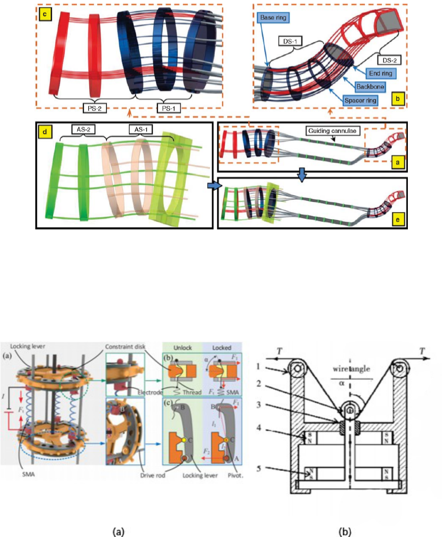
Dual continuum mechanism (DCM) is a purely mechanical structure (Figure 6) which has the
advantage of being easy to disinfect when removed from the actuated structure. By changing the
number and ordering of backbones, the mechanical properties of DCM are able to be changed
allodially according to different procedures. DCM’s actuation modularity leads to the invariance of its
actuation [
5
]. Xu et al. [
50
–
52
] proposed the robotic systems of the SJTU Unfoldable Robotic System
(SURS) robot for Single Port Laparoscopy (SPL) and endoscopic robotic testbed for Natural Orifice
Transluminal Endoscopic Surgery (NOTES), which used the DCMs to take shape their manipulation.
2.2.6. Comparison of the Structures of Continuum Robots
Some common structural types of CRS and their characteristics are introduced. Table 1
summarizes their structure and advantages.

Actuators 2020, 9, 142 7 of 30
Table 1. Table of comparison of the structures of CRs.
Structure Description Advantage
References
(Example)
Concentric Tube
Robot body consists of many pre-curved elastic tubes nested
together. Its shape can be controlled by the axial translation
and rotation of each tube seat.
Lightweight and slender. [38,39]
Tendon/Cable
Robot body consists of tendons/cables arranged along the axis
of the manipulator. The movement of CR is achieved by pulling
the tendon/cable.
Relatively easy to realize and control. [40–45]
Origami
The robot can be made into different origami shapes. Through the
crease layout, the robot’s telescopic details are designed.
Lightweight and easy to manufacture. [46]
Magnetic CR
Robot body consists of uniform soft polymer matrix and
uniformly dispersed magnetic particles. The operator controls
the external magnetic field through visual feedback to realize
the motion of CR.
Smaller size and high flexibility. [5,48]
Dual continuum
mechanism
DCM consists of 2 distal segments, 2 proximal segment and
some rigid guiding cannulae. Bending and length variations in
the distal portion cause the opposite change in the proximal portion.
Easy to disassemble and disinfect;
Mechanical properties can also be adjusted
freely for different procedures.
[50–52]
Actuators 2020, 9, 142 8 of 30
2.3. Variable Stiffness Methods
Stiffness modulation is a way in which artificial and natural soft structures are able to effectively
interact with the environment. For the past few years, many variable stiffness methods for CMs have
been researched and thus can be divided into three categories: mechanism-based, materials-based and
acoustic-based methods. Because most of the materials used to make the CR have low stiffness and are
prone to deformation under the influence of external forces, their stiffness cannot meet the requirement
of stable and controllable body size. The realization of variable stiffness not only enables the robot to
have high flexibility and flexible movement ability, but also can realize stable and controllable body
shape and certain output torque.
Figure 4. (a,b) Origami body; (c) Schematic diagram of the origami robot [46].
2.3.1. Mechanism-Based Variable Stiffness Methods
Mechanism-based variable stiffness methods (MVSMs) have been used in many previous
works, including antagonistic actuation, rack-locking mechanism, drive-rod-locking mechanism,
central-cable-tensioning mechanism, layer jamming and granular jamming [
53
]. The principle of
antagonistic actuation is to add the internal stress by applying a couple of forces in opposite directions.
Kim et al. [
54
] presented a CM for minimally invasive surgery that is able to modulate its stiffness
Actuators 2020, 9, 142 9 of 30
by simultaneously tensioning all the cables on the CM, whereas high tension can lead to structural
buckling. Stilli et al. [
55
] employed tendon-driven and pneumatic mechanisms so as to modulate CMs’
stiffness. The percentage change in stiffness reaches 156%. Yagi et al. [
56
] presented a rack-locking
mechanism for a flexible endoscope manipulator, which can augment rigidity by meshing the racks
embedded in adjacent segments. Sun et al. [
57
] presented a hybrid CR derived from pneumatic
muscles, with an elastic rod built in, which can be locked on the base of the CR to increase stiffness.
Degani et al. [
58
] proposed a central-cable-tensioning mechanism for the continuum endoscope,
the stiffness of which can be enhanced by the tension of the built-in cable through the robot’s center
axis. Chen Y et al. [
59
] designed a analogous mechanism for use in tension stiffening continuum tube
made of various spherical joints connected end-to-end. All of these mechanisms are feasible, but it is
still very difficult to distribute the tension in the built-in cable along the arm direction, which means
that the stiffness of each joint varies. This is especially obvious when the arm is bent. In addition,
these kinds of mechanisms would take up the central passage of CMs, making the path of the tube to
the end-effector difficult.
Figure 5.
(
a
) The magnetic response of submillimeter-scale ferromagnetic soft continuum robot;
(
b
) A demonstration of the active maneuverability of SFSCR navigation in complex vascular systems;
(c) Manifestation of active steering and navigating capabilities of SFSCR [48].
Yang et al. [
53
] proposed a MVSM based on SMA-spring for a novel rod-driven CR. The friction
along the drive rods is then adjusted by electric current applied to the SMA springs, so that the desired
robot configuration can be maintained. The structure of CR is stabilized by changing the friction on
the drive rod by applying electricity to the SMA springs. Figure 7a shows the leverage mechanism
for stiffness modulation. Zhang et al. in Reference [
60
] proposed a new type of permanent magnet
Actuators 2020, 9, 142 10 of 30
variable stiffness component, which can increase the adjustment range of stiffness without increasing
the driving torque of motor. Figure 7b shows the sectional view of variable stiffness device.
Due to the poor performance of the traditional parallel mechanism, Li et al. [
61
] proposed a
compact adjustable tube variable stiffness mechanism into the flexible parallel mechanism according
to clinical needs. The three prismatic-universal (3-PU) mechanism based on the superelastic NiTi
rod was adopted to realize the 3-DOF flexible motion. In this way, it largely improves the safety and
controllability of the operation.
Figure 6.
(
a–c
) The dual continuum mechanism with the proximal and distal segments; (
d,e
) The dual
continuum mechanism assembled into an actuation structure [5].
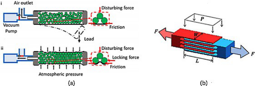
Many researchers have also focused on the phenomenon of particle or granule jamming.
Figure 8a shows the principle of particle jamming [
62
]. When air is pumped out of the capsule,
atmospheric pressure is applied to the particle system, leading to augmented interparticle forces and
system stiffness.
Figure 7.
(
a
) One segment of the structure of CR with Shape Memory Alloy (SMA) [
53
]; (
b
) 1—Crown
block; 2—Fall block; 3—Slide rail; 4—Fixed ring permanent magnet; 5—Moving ring permanent
magnet [60].
Actuators 2020, 9, 142 11 of 30
The jamming-based mechanism can improve the stiffness of the robot without changing the
shape and position. In References [
63
,
64
], the jamming-based mechanism is applied to the CRs.
The percentage change in stiffness reaches 925% [
63
] and 300% [
64
]. Both the minimally invasive
surgical arm proposed by Cianchetti M et al. [
64
–
66
] and the “FP7 STIFF-FLOP” surgical robot [
67
]
achieve variable stiffness in this way. However, the methods mentioned above is very likely to result
in less compact CRs. In addition to particle jamming, layered structure can also generate jamming
phenomenon, which is called layer jamming [
68
]. In References [
68
–
70
], the authors proposed layer
jamming mechanisms covering the surface of the snake-like and tail-like manipulators. The percentage
change in stiffness reaches 190% [
68
] and 156% [
69
]. The thin layers can keep the internal passage free
of obstruction but a vacuum pump was still required as an extra power source. For layer jamming
elements as shown in Figure 8b, when vacuum pressure is applied, the overlapping surfaces between
the layers provide considerable friction, thus increasing the pressure on the manipulator. In the
application process, the manipulator can not only achieve flexible movement (without vacuum),
but also achieve large carrying capacity (with vacuum) [
10
]. The thin layer keeps the internal channels
unimpeded, but still requires a vacuum pump as an additional power source [62].
Figure 8. (a) Principle of particle jamming [62]; (b) Diagram of layer jamming element [68].
2.3.2. Materials-Based Variable Stiffness Methods
Variable stiffness is an essential capability of CRs and soft material-based devices. The existing
material forms [
71
] mainly include Electro-rheological fluid (ERF), Magneto-rheological fluid
(MRF) [
72
–
74
], Low Melting Point Alloy (LMPA) [
75
,
76
], Shape Memory Polymer (SMP) [
77
,
78
],
Electro-active Polymer (EAP) [
79
], Thermoplastic Polymer (TP) [
80
,
81
], and so forth. Many researchers
use these materials through the control of magnetic field, electric field, temperature and other certain
conditions to make it in the liquid phase and solid phase mutual conversion, so as to control the
stiffness of the CRs and soft material-based devices.
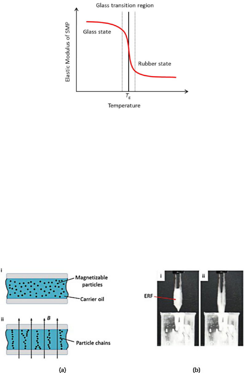
Glass/Phase Transition-Based Variable Stiffness Methods
In the variable stiffness methods of CRs, many researchers generally used the variable stiffness
methods based on glass transition or phase transition. The mechanical properties of thermoplastics
change with the thermal transformation of thermoplastics (glass transition (Tg) and melting transition
(Tm)). As is shown in Figure 9, elastic modulus of material occurs variation dramatically. When heat
it up to a temperature near the Tg value. This also happens when SMPs are heated [
82
]. When the
temperature is lower than Tg, SMP is in the glass state with high elastic modulus. But when the
temperature exceeds Tg, SMP transforms into rubber state, and SMP easily deforms.
Telleria et al. [
83
] and Cheng et al. [
84
] used the variable stiffness capability of solder to build
robots with heat-activated joints, but such materials have low safety due to their high melting point and
human body safety temperature. Wang et al. [
85
] proposed a single-hole robot manipulator with phase
transition-based variable stiffness method. They adopt the integrated design of structural materials,
Actuators 2020, 9, 142 12 of 30
which can integrate the variable stiffness material into the flexible joint and make it a part of the flexible
joint. The variable stiffness wrist can realize the rigid-flexible conversion during the operation.
Figure 9.
The change of Shape Memory Polymer’s (SMP) elastic modulus with temperature
variation [78].
Viscosity-Based Variable Stiffness Methods
MRF and ERF is also significant group of functional materials used for stiffness modulation in
the development of CRs or soft robots. The stiffness adjustment of MRF and ERF is based on the
principle that the viscosity and yield stress of fluid vary with the change of applied magnetic field
or electric field. Figure 10a shows that the microstructure of MRF without and with magnetic fields.
Under the application of magnetic field, the magnetized particles in the carrier oil form chains along
the direction of magnetic flux, and the viscosity and shear modulus of the fluid transform accordingly.
This also occurs in ERF, which contains electrically active particles, while MRF uses magnetizable
particles. As shown in Figure 10b, ERF changes from a high viscosity gel state to a low viscosity liquid
state (with or without applied electric field) [
86
]. Taniguchi H et al. [
72
] proposed a mobile robot with
variable stiffness. The driving leg was made of rubber sleeve wrapped with MRF, and the deformation
and variable stiffness of the driving leg could be controlled by external strengthening of magnetic field.
This method can realize the conversion between solid state and liquid state, and the response speed is
fast, but it needs a strong magnetic field to drive, and the safety performance is a factor that needs to
be considered.
Figure 10.
Fragments of stiffness modulation methods. (
a
) Viscosity-based stiffness modulation methods [
87
];
(b) ER fluid sat different states [86].
Actuators 2020, 9, 142 13 of 30
Comparison of Materials-Based Variable Stiffness Methods
According to the materials-based variable stiffness methods, we can divide it into three categories:
glass transition-based, phase transition-based and viscosity-based variable stiffness methods. Table 2.
simply lists the comparison of materials-based variable stiffness methods.
Table 2. Table of comparison of materials-based variable stiffness methods.
Methods Transition Time Young’s Modulus Deformation
Glass transition-based Change with the environment General Mainly bending
Phase transition-based >15 s Relatively large Mainly tensile deformation
Viscosity-based - Relatively small Bending
2.3.3. Acoustic-Based Variable Stiffness Method
In addition to the above two categories of variable stiffness methods, Yang et al. [
10
]
proposed acoustic-based method as a potential variable stiffness method. Acoustic waves
can change the arrangement of particles to produce different effects (unjamming or jamming).
Therefore, acoustic-based method can be used to change the arrangement of particles to change the
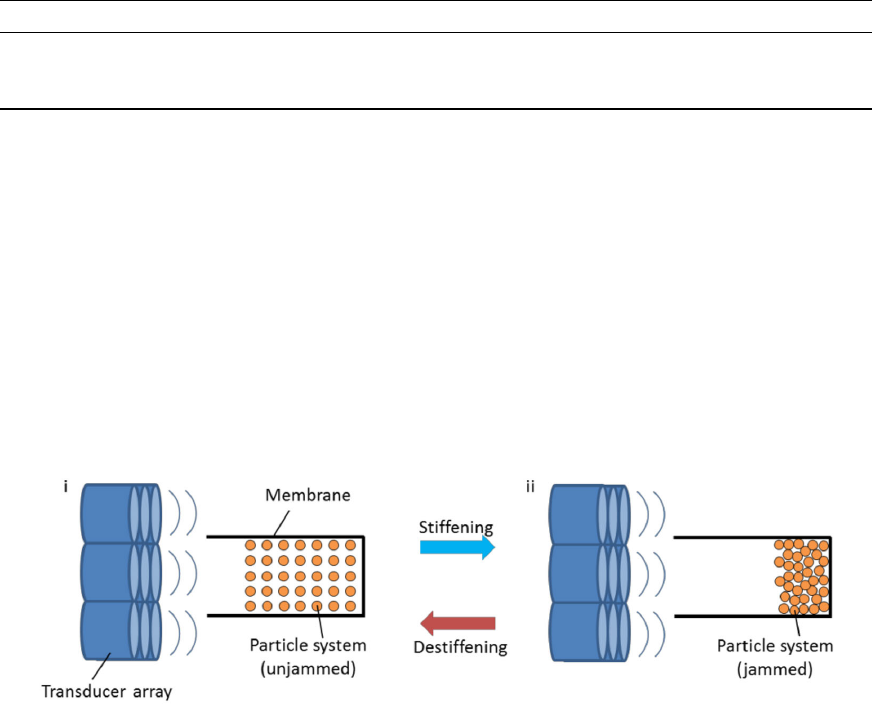
stiffness of particle packets. As is shown in Figure 11, by changing the sound field distribution through
transducer array, the particle system state changes from unjammed state to jammed state, and the
interval between particles becomes smaller, thus increasing the stiffness of system. This acoustic-based
variable stiffness method requires careful selection of particle materials and membrane materials,
further study of transducer array and reflector structure and improvement of power density of
acoustic manipulation.
Figure 11.
The principle of acoustic-based variable stiffness method [
10
]. (
i
) Loose particle alignment
results in low stiffness of the system; (
ii
) The acoustic field makes particles compact and leads to high
stiffness of the system.
2.3.4. Comparison of Variable Stiffness Methods
At present, the variable stiffness methods commonly used in CRs mainly include the above
mentioned methods. The methods based on antagonistic actuation is relatively simple and does not
require other additional media. But compared with the material-based method, the variable stiffness
effect is poor and can be applied in light load situations such as human-computer interaction. The layer
jamming mode increases the friction and antagonism between the lamellar materials through negative
pressure, so as to improve the structural stiffness. However, the layer structure will have a certain
effect on the flexibility of the soft manipulator. Viscosity-based and glass/phase transition-based
methods achieve variable stiffness by imposing physical field and making the material change
phase. The variable stiffness effect is good, but it has difficulty in realizing arbitrary variation of
the mechanism’s stiffness. Compared with other variable stiffness methods, mechanism-based variable
stiffness methods usually have complex mechanism design, which may complicate the fabrication and

Actuators 2020, 9, 142 14 of 30
control of these mechanisms. Table 3. summarizes common variable-stiffness methods and compares
them [10]. Stiffness range represents the percentage change in stiffness in the Table 3.
Table 3. Table of comparison of variable stiffness methods.
Variable Stiffness Methods Type of Control Principle Stiffness Range
Antagonistic actuation Driving force Antagonism Small
Jamming-based Pressure Interparticle fiction Wide
Layer jamming-based Pressure Interlayer friction Small
Glass/phase transition-based Thermal energy Glass transition, phase transition Do not adjust
Viscosity-based Electric/magnetic field Viscosity change Do not adjust
Acoustic-based Frequency Acoustic field variation Be further studied
3. Actuation Methods for Continuum Robot
We define the actuation of the robot as the process of converting other forms of energy into
the power to make the robot realize certain movements [
20
]. Due to its own flexible structural
characteristics and infinite DOF, it is significantly different from traditional rigid robots in actuation.
The traditional rigid robot mainly relies on the built-in motor and gear system to drive. Such driving
method will affect the flexibility CRs. The principle of CR’s actuation should guarantee the stiffness
requirements and compliance with the application environment such as the organ tissue while the robot
applied to the Surgery or the magnetic fields while Cooperated with MRI under the premise of satisfy
the actuation requirements. Common actuation methods for CRs include concentric tube transmission,
tendon/cable driven, pneumatic/hydraulic driven, smart material driven and Magnetic actuation.
3.1. Concentric Tube Transmission
Concentric tube robots are typically composed of nested pre-curved tubes and each independent
concentric tube has 2-DOF [
88
,
89
]. Concentric tube robots realize bending and twisting relying on
the combined action caused by the relatively independent motion of each tube. Through the mutual
movement and rotation of multiple tubes, the overall shape of the robot could be changed to change the
spatial posture. When applied in minimally invasive surgery, the semi-rigid structure of the concentric
tube robot not only makes it flexible, but also ensures that the motion of the concentric tube in the
organ tissue can resist the interference of external forces appropriately [
90
,
91
]. The great potential of
concentric tube robots in medical field has been widely appreciated in recent years. The actuation
of the concentric tube robot also depends on the concentric tube structure. The energy source for
its movement can be input from external energy equipment such as motor. Of course, it can be
driven manually. The most remarkable feature of concentric tube robots’ actuation system is cascaded.
A cascaded actuation system can be matched with the concentric tube structure of the robot to realize
the hierarchical transmission of the concentric tube robot. It also makes the robots actuation system
more compact and miniature [
92
,
93
]. Morimot [
94
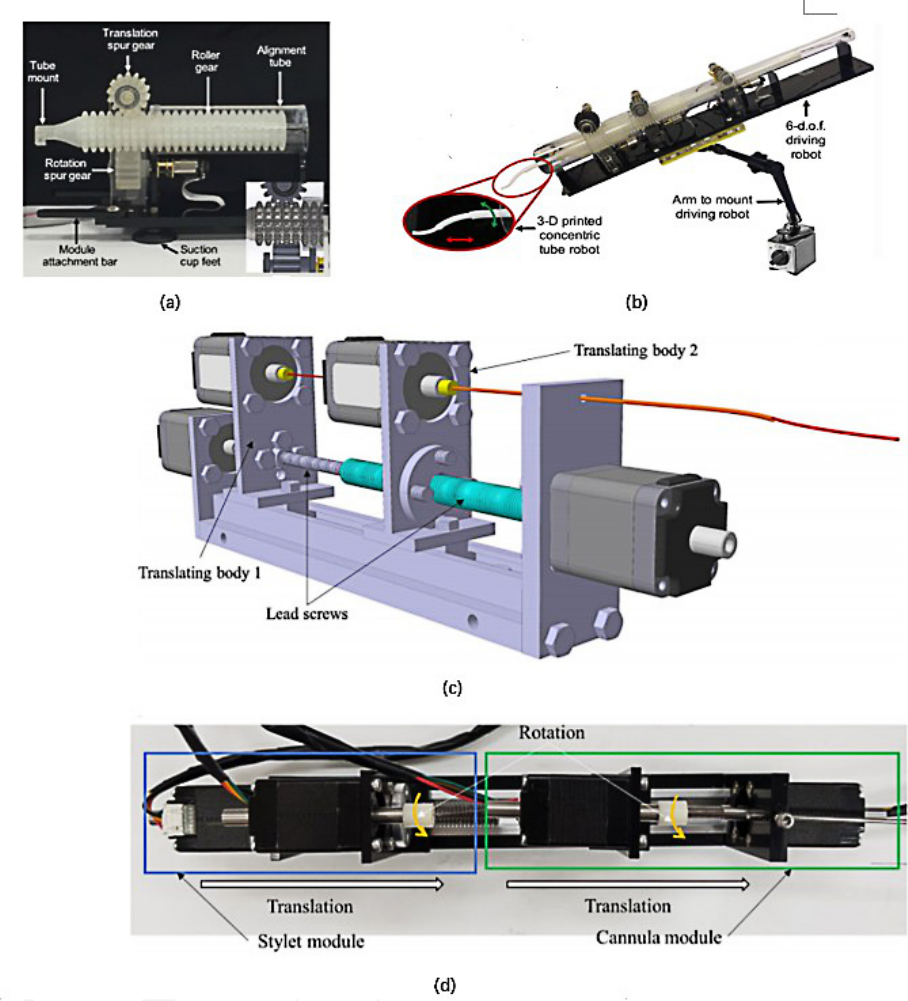
] and his colleagues at Stanford University used 3D
printing to create a three-tube concentric robot with modules separated from each other for surgical
operations (Figure 12b). A drive system composing of a roller gear with teeth in both the axial and
radial directions and two spur gears that are perpendicular to each other is integrated in each module.
Through the independent coupling motion between the gears in each drive system, the rotation and
translation of each module can be realized to meet the demands of different operations.
Farooq Muhammad Umai et al. [
95
] from Chonnam Natl Univ also designed a nested concentric
tube robot based on cascaded actuation modules. They propose a novel actuation system (shown in
Figure 12c) using motors for CTR actuation. The characteristic of the motor compose of a hollow
shaft.The tubes’ proximal end will be gripped and the rest of tube pass through the hollow shaft. In this
way, the different part of CTR will stay in line to avoid buckling and torsional windup. This nested
conical tube robot contains a Stylet module and a Cannula module. This drive system using a total of
four motor, of which 2 are used for translation and 2 for rotation. Four motors are used to drive the
Stylet Module and the Cannula Module, each with two degrees of freedom.
Actuators 2020, 9, 142 15 of 30
Figure 12.
(
a
,
b
) Three-tube concentric robot [
94
]; (
c
) Schematic diagram of the driving system of the
concentric tube robot; (d) Top view of the drive system [95].
3.2. Tendon/Cable Driven
The tendon/cable drive was inspired by biology. The robot body is driven by the contraction
and stretching of the tendon or cable driven by the motor [
43
]. In recent years, the breakthrough in
the way of tendon driving is to realize the classification of robot driving. The tendon-driven CRs is
usually divided into distal and proximal parts. The distal and proximal control do not affect each
other, which can improve the accuracy of robot motion control. Today’s CRs based on tendon driven
are typically constructed with tendons embedded in the robot body and a flexible skeleton (usually
a spring) at the center. Li, Minhan et al. [
96
] proposed a tendon driven, including the manipulator
part and actuation part. The movement of the robot will be realized through the cooperation of these
two modules. The actuation part composes of a distal module and a proximal module (Figure 13).
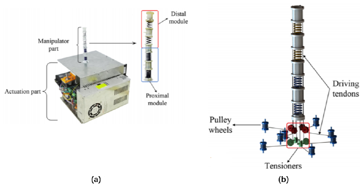
Actuators 2020, 9, 142 16 of 30
Every module composes of two springs, connecting plates and four tendons. The tendons are wound
around the eight pulley wheels driven by the independent stepping motors. The pulley wheels and
motors are placed in the actuation part. The rotation of the motor will be transformed into the linear
motion of the tendon through the pulley wheels. The connecting plates are used to connect the springs
and guide the tendons. Because the four tendons in the distal module will pass through the proximal
module, eight guide holes in the connector plate are designed to guide the tendons. Used as the center
backbone of the robot, springs are able to achieve a linear change in length following the linear force.
At the same time, it is possible to use springs to achieve variable stiffness along the robot length o
different spring constants. For example, the distal module employs a spring with the lower spring
constant (3 N/mm) than the proximal one (5 N/mm). This is the most significant advantage of this
drive system, consistent with the design principles of variable stiffness for continuous robots [63].
Figure 13.
(
a
) The four parts of the tenon-driven CR are divided into distal and proximal modules;
(b) The tendon is embedded in the body of the robot and is separated from the motor [96].
3.3. Pneumatic/Hydraulic
Fluid driven is the most common and mature type of actuation for CRs. The traditional fluid
driven is to achieve deformation and movement by piping in the fluid such as gas and liquid by making
the inner cavity of the CRs contract or expand [
97
]. Therefore, an external gas/liquid pump and some
fluid pipe are necessary for a fluid driven CRs. Such equipment always possess a large volume, which
brings difficulties to the integration of the CRs. At the same time, conventional robots require complex
electronic components to achieve control functions, which limits their application areas to a certain
extent, such as in flammable environments with high-temperature gases. Conventional gas/liquid
actuation have been well developed and there is a lot of paper on them. This part mainly narrate
some CRs based on new fluid actuation method that overcomes the defect of traditional gas
actuation method.
Pneumatic actuation is widely used in CRs. It can be divided into positive pressure actuation
and negative pressure actuation. The positive pressure actuation is to make the cavity expand
with the movement and deformation of the flexible actuator by filling the compressed gas into the
cavity. Negative pressure actuation refers to the extraction of air from the cavity, which causes
the cavity to contract and drives the movement and deformation of the software actuator [
17
].
Besides, pneumatic soft systems can require high power-to-weight ratios. A major disadvantage of soft
pneumatic robots is that their stiffness cannot vary independently of the position of their end-effector
in space. Xiang et al. [
98
] presented the novel robot arm successfully decouples its end-effector
positioning from its stiffness. The arm combines the high payload to weight ratio, light weight and
pneumatic robustness with versatility and adaptability of stiffness modulation. Robertson et al. [
99
]
Actuators 2020, 9, 142 17 of 30
presented a single 3-DOF module to set up the baseline performance and characterized attributes of a
completely comprehensive hybrid robotic system combining the design methods of pneumatics and
origami mechanism as shown in Figure 14a. Joseph D. Greer [
100
] et al. proposed a soft continuum
robot based on Series Pneumatic Artificial Muscles (sPAMs) (shown in Figure 15). The robot contains
3 axially distributed sPAMs and a tubular pneumatic backbone. SPAMs act as actuator. A sPAM
is made from many thin rectangular sheets of polyethylene tubes. The original state is deflated.
When inflated, the SPAMs are tightened, exerting a tension force on the robot’s pneumatic backbone,
causing bending to work. Tani Kosuke [
101
] of the Tokyo Institute of Technology proposed a CRs
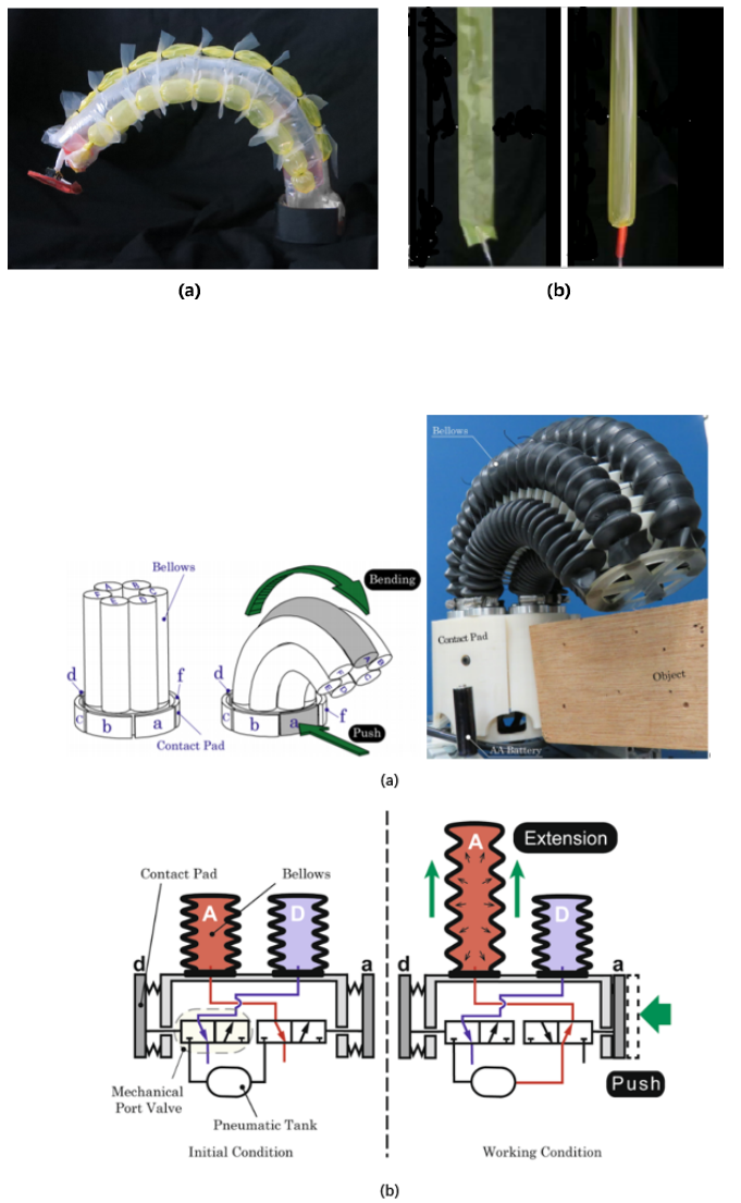
consists of six bellows connected externally with a miniature air pump. The bellows bend based on
mechanical reactive system and do not require any electronic equipment. The driving principle is
shown in Figure 16. The change in the length of the bellows under air pressure causes the robot to
bend and grasp the objects. This electronicless actuation methods expands the range of applications
for robots.
Figure 14.
(
a
) Soft pneumatic origami-inspired robot [
99
]. (
b
) Internal and external structure of the
robot [102].
The CRs using pneumatic actuation has the advantages of fast reaction speed, fast deformation,
light weight, but at the same time there are also some shortcomings: (a) To obtain high seal, it is difficult
to achieve the miniaturization of the drive equipment, the need for external gas pipe, air compressor
and other complex structure; (b) The air cavity in the inflatable expansion will burst and so on if you
do not add the limit layer. Therefore, the pneumatic actuator still needs to be optimized and innovated.
Actuators 2020, 9, 142 18 of 30
Figure 15.
(
a
) Schematic diagram of Series Pneumatic Artificial Muscles (sPAMs) continuum robot;
(
b
) Two different states of pneumatic muscles, the left is the deflated state, the right is the inflated
state [100].
Figure 16. (a) The pneumatic CR consists of six identical bellows; (b) Diagram of value [101].
3.4. Smart Materials Driven
The common actuation way of CRs usually requires external motor to provide energy Which
is connected to the body of CRs by circuit and will undoubtedly affect the flexibility of CRs.
Smart material actuation has emerged in recent 30 years [
38
]. The commonly intelligent materials
including SMA, EAP, DEA, and so forth [
103
–
105
]. Because the intelligent material can be used as a
CRs ontology or embedded in the robot body without rigid motor, and the energy source can be natural
energy such as light, temperature or humidity. Smart materials actuation can achieve the integration
Actuators 2020, 9, 142 19 of 30
of CRs and driven system as well as the flexibility. DEA, EAP, IPMC and other actuation material need
external electric field to complete driving due to their own properties, which limits the application
scope of CRs based on smart material driven to some extent. So in recent years, scientists have been
looking for new CRs actuation materials.
Shape Memory Alloy (SMA) is a kind of material composed of more than two kinds of metal
elements. Its mass is small, and easy to realize the miniaturization automation and noise-free working
of the actuator. The driving principle of SMA is to change the high temperature austenite into the low
temperature martensite under the high temperature, and its original shape is damaged and deformed,
which drives the robot to move. The driving energy of SMA need not completely rely on electric
field, but also change the temperature of the robot body with the help of light energy [
106
]. At the
same time, the electrothermal effect of SMA has the defect as low drive frequency, which limits the
movement of CRs. Kim et al. in Reference [
107
] have proposed a method that relies on the optical
effect of SMA, which is still based on optothermal and optical trapping effects of laser to cause
temperature change, but higher sensitivity compared to the traditional thermo effects. The micro-robot
is controlled by a laser that provides wireless space and time selection. During the actuation process,
the robot exhibits crawling movements, including those triggered by the SMA, to remove the surface
adhesion, photothermal, and propulsion caused by the optical trap effect. Optical driving does not
require wires and pipes, as electric drives do, nor do magnetic driving require many external devices,
making robotic systems more autonomous and lightweight. As an unfettered stimulus, light can be
more flexible to drive the robot. In addition to driving based on thermal effect, optical driving can also
be actuated directly through optical effect with the help of photosensitive materials. Alcaide et al. [
102
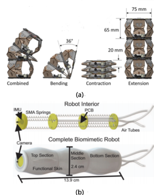
]
used SMA springs and silica gel to make a three-stage worm-like robot. The robot was composed
of three identical parts, each with three SMA springs at 120 degrees and made of silicone skin,
as shown in Figure 14b. For the purpose of enhancing the operational capability of CRs in finite space,
Tian et al. [108] proposed a new central support structure with the spiral cutting mode. By analyzing
the different cutting modes of thin-wall tube of superelastic NiTi SMA, the spiral hollow scheme was
chose. The spiral hollow scheme was selected through analysing different cutting patterns of the
thin-walled superelastic NiTi SMA tube. For the sake of providing a reference for the design and
modelling methods, they systematically introduced from design method to manufacturing process
of the central support structure using superelastic NiTi SMA material. Due to the advantages of
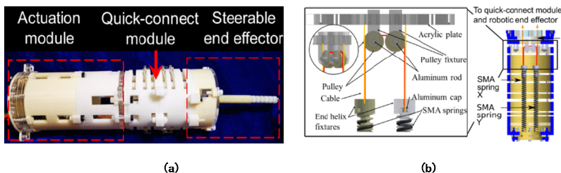
SMA spring with high power density, compact structure and MRI-compatibility, Shao et al. [
104
]
proposed SMA spring-based actuation module and integrated it with quick-connect module and
steerable end-effcetor into a highly compact and adaptable MRI-condition system, thus simplifying
the surgical procedure of MRI room. Each drive cable is connected to the SMA spring through the end
helically-threaded fixture so that the cable ends with the aluminum cap fixed in the clamp and the
SMA spring is tightened on the clamp (as shown in Figure 17). In conclusion, SMA actuation structure
is light in weight and can be miniaturized, but the temperature is difficult to control and the drive
frequency is low.
Figure 17.
(
a
) Prototype of the SMA-actuated neurosurgical robot composed of three modules;
(b) Detailed composition of the actuation module [104].
Actuators 2020, 9, 142 20 of 30
Jiaxin Shi of Peking University prepared GO (GO)/rGO (reduced GO) Janus films with a thickness
of 15 um using laser direct writing technology. This film can respond to change in environmental
humidity, and the reaction effect is best at a thickness of 15 um. A leaf grabber was prepared by using
this actuator to grasp leaves in humid environment. This overcomes the problem that traditional
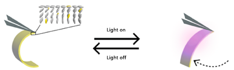
intelligent material is difficult to arrange electric field in humid environment. Marina et al. developed
a light driven robot with liquid crystal network (LCN) as the raw material. The robot uses an external
LED as the power source. When driven by specific wavelength light, the robot legs made of liquid
crystal network will be deformed as shown in Figure 18 to push the robot forward. In addition to the
simplicity of the driving system, light driving has a higher driving efficiency than electric driving [
109
].
Figure 18. The transformation of a robot under light [109].
3.5. Magnetic Actuation
Magnetic driven is a remote controlled way to control and navigate the robot motion.
Because magnetic fields can transmit energy wirelessly, the robot’s driven system is very light.
At present, the magnetic drive of robot depends on the arrangement of magnetic field on one hand
and the application of magnetic material on the other hand [
110
,
111
]. Joyee et al. [
112
] proposed a
soft robot based on magnetic drive, which is inspired by inchworm in nature. This robot imitates the
shape and movement mechanism of inchworm and is manufactured by 3D printing. The driving of
the robot depends on the cooperation of magnetic field and hysteresis friction. Through the reasonable
arrangement of magnets, the friction between the robot’s leg and the substrate can be controlled,
and the crawling movement of the robot can be realized.
Xiang et al. in Reference [
113
] also used three-dimensional Helmholtz coil to construct a uniform
magnetic field in any direction of space and controlled various motion states of the micro-CRs based on
magneto-elastic composite materials by using the uniform magnetic field. The structure of the crawling
robot is shown in Figure 19d. Its head and tail are made of two magnetic materials with the same size
and opposite magnetization direction. The middle part is made of elastic material, which is referred
to as joint later. If there is no magnetic field, the robot is in a natural flat state. When the external
magnetic field intensity is not zero, the robot is subjected to magnetic torque, gravity, supporting force,
friction and other external forces, and its body is bent into arch. And when the external force reaches a
certain degree, the robot can make various actions.
The magnetic actuation can produce high-speed motion output and force output, but the
traditional magnetic drive is equipped with a magnetic field generator outside, which will make
the robot structure less compact. At the same time, the biggest disadvantage of the magnetic drive
is that the robot’s motion range will be limited to the magnetic field working area, which brings
great restrictions to the robot’s motion. At present, the main research center of magnetic actuation
is the combination of imaging technology and the search for biodegradable magnetic materials to
improve the application of magnetic driven robots in medical surgery. In addition, finding a magnetic
field generator with a wider coverage is also the direction of future efforts. As a driving method
that can realize remote control, magnetic actuation has great potential in the medical field. At the
same time, magnetic actuation is more accurate than other driving methods. When this kind of robot

Actuators 2020, 9, 142 21 of 30
develops to a certain extent, it can be used to avoid the pain and damage to the human body caused
by surgical wounds.
Figure 19.
(
a
) The model of the 3D printed robot; (
b
,
c
) The state of a robot at rest and bent; (
d
,
e
) A full
one-step crawl consists of a continuous contraction and stretch [112,113].
3.6. Comparison of the Actuation of Continuum Robots
To sum up, we have introduced the common types of actuation of CRs in recent years. Table 4.
summarizes the actuation methods and their advantages.

Actuators 2020, 9, 142 22 of 30
Table 4. Table of comparison of actuation methods of CRs.
Actuation
Method
Description Advantage
Concentric tube
transmission
[88–95]
Concentric tube robots are typically composed of nested precurved
tubes and each independent concentric tube has 2-DOF.
Concentric tube robots realize bending and twisting relying on the
combined action caused by the relatively independent motion of
each tube. The actuation system of Concentric tube robots is always
modular and cascaded.
1. Because of the independent motion and
mutual cooperate of each tube, the robot
motion has high dexterity and high DOF.
2. High accessibility to narrow space(such as
human body).
3. The modular and cascaded design is
beneficial for the compactness and
miniaturization of the robot.
Tendon/cable
driven [43,63,96]
Tendon-driven robots usually have an elastic and compliant
backbone. The robot body is driven by the contraction and
stretching of the tendon or cable driven by the motor.
1.The elastic backbone is easily to realizing
interaction with constrained environment.
2. Robot has more compact size which,
provide more position accuracy and more,
operation precision in constrained space.
Pneumatic
[97–101]
The principle of pneumatic is to cause the movement of the robot
body with the help of the contraction and expansion of air cavity
caused by inflation and deflation .
1. Fast reaction speed and fast deformation.
2. The weight of robot body is light and the
structure is simple.
Smart materials
driven [102–109]
Smart materials are usually used as raw materials for robots and
play a role in the movement of robots. Under external stimuli, the robot
will perform expected actions due to the properties of the material.
1. High simplicity of the actuation system.
2. High energy efficiency.
Magnetic
actuation
[110–113]
The robot realize expected motion under the magnetic field with
the help of the arrangement of magnetic field and the application
of magnetic material.
1. The magnetic actuation can produce
high-speed motion output and force output.
2. Easily to realize remote wirelessly control.
Actuators 2020, 9, 142 23 of 30
4. Future Research Challenges and Conclusions
4.1. Robot Ethics
Artificial intelligence has always been a topic full of controversy. Many applications of artificial
intelligence in the medical field are embodied in the form of robots. The ethical issues of medical
robots should receive corresponding attention as technology advances. Here, the ethical issues of
medical robots are described from three aspects: safety issues, liability laws, and doctor-patient
relationship [114–116].
The investment in continuum robots in the medical field is to achieve safer and more efficient
completion of medical work, so the research and development of medical robots should take safety as
the primary goal. Whether the mechanical structure and control strategy of the robot, today’s research
is quite mature. However, accidents involving robots injuring people still occur occasionally. If surgical
robots have inaccurate recognition or movement deviations during their work, the harm to patients
could be immeasurable. The second is the legal liability of medical robots. If a medical accident occurs
during the process of assisted treatment or even independent treatment, who should bear the legal
responsibility for the accident. The investigation of legal responsibility has always been one of the
ethics that robot researchers care about. Finally, the treatment of the doctor-patient relationship should
be valued. In recent years, the tension between doctors and patients has become a factor hindering
people’s livelihood and health. Even the surgical robot is powerful enough to complete medical tasks
independently, the robot’s cold personality may not be able to complete the communication with the
patient. And the psychological problems of the patient during the treatment process may be ignored,
which will cause the patient to resist the robot doctor. This will undoubtedly make the doctor-patient
relationship more tense.
4.2. Miniaturization and Modularity
Narrow spaces such as earthquake ruins and internal organs are important application scenarios
for CRs. This requires robots to have good flexibility and a small enough volume to fit into the narrow
space. Therefore, miniaturization is an important means to promote large-scale applications of CRs in
the future. One of the important means to achieve miniaturization is modular design. The cascade
design of the concentric tube robot is a manifestation of modularity. In recent years, the application of
foldable structures such as paper folding mechanisms has also been applied in CRs, which also reflect
the modularity. The modular design can make the volume of the CRs contractible, which is of great
significance for the motion and control of the CRs in a complex and narrow space.
4.3. Variable Stiffness and Self-Adaptive
The flexibility of the CRs makes it have good environmental adaptability, but it also brings the
disadvantage of low structural rigidity [
117
]. Therefore, when the robot receives a large external load
or outputs a large force, it is prone to large deformation. This has a great impact on the robot’s motion
accuracy and control accuracy. Therefore, the realization of the variable stiffness of the robot is of great
significance. When outputting a large force or the end effector bearing a large load, if the robot can
have a large rigidity, it can meet the needs of the user. At the same time, the realization of the robot/s
variable stiffness often means that the robot has better adaptive capabilities. The landing of a CRs
needs to consider application scenarios. Different application scenarios require different stiffness of
the CRs. Therefore, variable stiffness is an important means to improve the robot’s adaptive ability to
the environment.
4.4. Biocompatible Design
Biocompatibility is very important in CRs, especially those that operate deep in the human
body [
118
]. The medical application of CRs shows an attractive prospect. Therefore, compared with
other robots, CRs require good biocompatibility. To achieve this performance, both materials and
Actuators 2020, 9, 142 24 of 30
structure should be paid attention to References [
119
–
121
]. For example, the use of smoother material
to construct the robot body, such as hydrogel, on the one hand can reduce the damage to human
tissues when moving in the human body, on the other hand, a smoother surface can also reduce
friction with the human agile action and fast motion. It realizes the use of non-toxic materials that
can be automatically degraded in the body to construct the robot body, which is used to enter the
human body for targeted drug treatment or wound repair. This is also a means of “implanted medical”.
Using animal cells to construct a living robot can realize automatic healing after surgery (such as tumor
removal), and even promote the growth of human cells. The use of living cells to construct robots is of
great significance to “regenerative medicine”. As for structure, we could design the robot’s torso and
skeleton according to the position of human organs to avoid damage to human organs. At the same
time, a more flexible body could flexibly change its position and shape in the human body with the
operation of the doctor, so as to better complete the task.
4.5. Electric Drive
The existing actuation methods of CRs have different disadvantages. The muscles of natural
organisms are directly driven by motor neuron firing. This driving method has the advantages
of precise control, variable shape and rigidity of muscle groups. This driving method also has
significant advantages for CRs. Researching out a new driving method relying on electric energy is
the development trend of CRs driving in the future [
122
]. Electric actuation is easily restricted by the
environment. For example, the interference of electric ions in humid and magnetic environments will
affect the accuracy and reliability of the actuation. Therefore, how to overcome these limitations while
taking advantage of the electric drive is a challenge for the future.
The CRs has unlimited potential in medical applications for its compliance and accessibility,
especially minimally invasive surgery. In the future, the development of CRs and medical development
will promote each other, which will also accelerate the commercial application of CRs technology and
better benefit mankind.
4.6. Living Cell Actuation
CRs driven by living cells are also a trend of robot-actuation in the future. Embedding living cells
such as cardiomyocytes and skeletal muscle cells into the body of the robots, and using other flexible
materials as the structural matrix to construct the body of the robot, CRs can exhibit the realized
movement and work ability while possessing Better biocompatibility. At present, driving methods
that rely on living cells usually require external stimulation such as light, electricity, and magnetism.
Under external stimulation, the elongation and contraction of living cells will cause the shape change
of the structural matrix, which will cause the robot to move. This kind of robots are called ’biohybrid
robot’ [
123
]. At present, the bottleneck restricting the development of biological hybrid robots is the
scarcity of cell sources on the one hand, and the choice of matrix materials for the robot structure on
the other hand. In response to the first question, relying on the differentiation of stem cells is currently
a more mainstream method, but it is still in the immature stage. For the matrix material, it needs to
meet the requirements of biocompatibility, flexibility, stability and so on, which not only depends on
the search for new materials, but also on synthesis.
4.7. Conclusions
This paper summarizes the design and actuation principles and structural characteristics of the
continuum robots in recent years. It focuses on the medical application of continuum robots. At the
end of the article, the ethics of medical robot and future development as well as challenge of continuum
robots have been discussed.
The continuum robot has unlimited potential in medical applications for its compliance and
accessibility, especially minimally invasive surgery. In the future, the development of continuum
Actuators 2020, 9, 142 25 of 30
robots and medical development will promote each other, which will also accelerate the commercial
application of continuum robot technology and better benefit mankind.
Author Contributions:
Y.Z. designed the overall paper. L.H. and Y.X. helped to write the manuscript.
Y.Z. supervised the paper. All authors commented on the paper. All authors have read and agreed to the
published version of the manuscript.
Funding:
This research was supported by the Strategic Priority Research Program of the Chinese Academy of
Sciences (class A) (Grant No. XDA22040203), the Fundamental Research Funds for the Central Universities
(Grant No. 2019XX01), GDNRC[2020]031, and the Natural Science Foundation of Guangdong Province (Grant No.
2020A1515010621).
Conflicts of Interest: The authors declare no conflict of interest.
References
1.
Zhang, W.; Li, Y.; Kong, W.; Tinavi Medical Technologies Co., Ltd. Precision Detection Method and Device
for Surgical Robot Positioning System. U.S. Patent Application US20200163725A1, 28 May 2020.
2.
Siegfarth, M.; Pusch, T.P.; Pfeil, A.; Renaud, P.; Stallkamp, J. Multi-material 3D printed hydraulic actuator for
medical robots. Rapid Prototyp. J. 2020, 26. [CrossRef]
3.
Zhang, Y.; Lu, M. A review of recent advancements in soft and flexible robots for medical applications. Int. J.
Med Robot. Comput. Assist. Surg. 2020, 16, e2096.
4.
Bottger, S.; Callar, T.; Schweikard, A.; Ruckert, E. Medical robotics simulation framework for
application-specific optimal kinematics. Curr. Dir. Biomed. Eng. 2019, 5, 145–148.
5.
Jiangran, Z.; Bo, F.; Min-Hua, Z.; Kai, X. Surgical robots for SPL and NOTES: A review. MITAT Off. J. Soc.
Minim. Invasive Ther. 2015, 24, 8–17.
6. Anderson, V.C.; Horn, R.C. Tensor arm manipulator design. Trans. ASME 1967, DE-57, 1–12.
7.
Robert, J.W. Design and Kinematic Modeling of Constant Curvature Continuum Robots: A Review. Int. J.
Robot. Res. 2010, 29, 1661–1683.
8.
Kumar, S.P.; Krishna, C.M. Continuum Arm Robotic Manipulator: A Review. Univers. J. Mech. Eng.
2014
,
2, 193–198.
9.
Manti, M.; Cacucciolo, V.; Cianchetti, M. Stiffening in Soft Robotics: A Review of the State of the Art.
IEEE Robot. Autom. Mag. 2016, 23, 93–106.
10.
Yang, Y.; Li, Y.; Chen, Y. Principles and methods for stiffness modulation in soft robot design and
development. Bio-Des. Manuf. 2018, 1, 14–25.
11.
Hannan, M.W.; Walker, I.D. Kinematics and the implementation of an elephant’s trunk manipulator and
other continuum style robots. J. Robot. Syst. 2003, 20, 45–63.
12.
Smith, K.K.; Runks, W.M. Tongues, and tentacles-moving with skeletons of muscle. Am. Sci.
1989
, 77, 28–35.
13.
Qiang, Z.; Yongheng, Y. Research status and prospects of bionic continuum robots. Mach. Des.
2009
, 26, 1–6.
14. Margheri, L.; Laschi, C.; Mazzolai, B. Soft robotic arm inspired by the octopus: I. From biological functions
to artificial requirements. Bioinspir. Biomimetics 2012, 7, 025004.
15.
Mazzolai, B.; Margheri, L.; Dario, P.; Laschi, C. Measurements of octopus arm elongation: Evidence of
differences by body size and gender. J. Exp. Mar. Biol. Ecol. 2013, 447, 160–164.
16.
Mazzolai, B.; Margheri, L.; Cianchetti, M.; Dario, P.; Laschi, C. Soft-robotic arm inspired by the octopus: II.
From631 artificial requirements to innovative technological solutions. Bioinspir. Biomimetics 2012, 7, 025005.
17.
Jihong, Y.; Peipei, S.; Xinbin, Z.; Jie, Z. Summary of research and development on bionic mechanism,
drive and modeling control of soft manipulator. Chin. J. Mech. Eng. 2018, 54, 1–14.
18.
Cianvchetti, M.; Arienti, A.; Follador, M.; Mazzolai, B.; Dario, P.; Laschi, C. Design concept and validation of
a robotic arm inspired by the octopus. Mater. Sci. Eng. C 2011, 31, 1230–1239.
19.
Robinson, G.; Davies, J.B.C. Continuum robots-a state of the artC. In Proceedings of the IEEE International
Conference on Robotics and Automation Michigan, Detroit, MI, USA, 10–15 May 1999.
20.
Burgner-Kahrs, J.; Rucker, D.C. Continuum Robots for Medical Applications: A Survey. IEEE Trans. Robot.
2015, 31, 1261–1280.
21. Lining, S.; Haiyan, H.; Mantian, L. Summary of continuous robot research. Robot 2010, 32, 688–694.
22.
Kolachalama, S.; Lakshmanan, S.; Wang, W. Continuum Robots for Manipulation Applications: A Survey.
J. Robot. 2020, 2020, 4187048.
Actuators 2020, 9, 142 26 of 30
23.
Jones, B.A.; McMahan, W.; Walker, I. Design and analysis of a novel pneumatic manipulator. IFAC Proc. Vol.
2004, 37, 687–692. [CrossRef]
24.
Laschi, C.; Cianchetti, M.; Mazzolai, B.; Margheri, L.; Follador, M.; Dario, P. Soft robot arm inspired by the
Octopus. Adv. Robot. 2012, 26, 709–727. [CrossRef]
25.
Xu, S.; Li, G.; Song, D.; Sun, L.; Liu, J. Real-time shape recognition of a deformable link by using a
self-organizing map. In Proceedings of the IEEE 14th International Conference on Automation Science and
Engineering (CASE), Munich, Germany, 20–24 August 2018; pp. 586–591.
26.
Shikari, A.; Asada, H. Triple scissor extender robot arm: A solution to the last one foot problem of
manipulation. IEEE Robot. Autom. Lett. 2018, 3, 3975–3982. [CrossRef]
27.
Niu, G.; Wang, J.; Xu, K. Model analysis for a continuum aircraft fuel tank inspection robot based on the
Rzeppa universaljoint. Adv. Mech. Eng. 2018, 10, 5. [CrossRef]
28.
Zheng, Z.; Wang, K.; Wu, X.; Zhang, Q.; Li, K. Dynamic analysis of elastic projecting robot inspired by
chameleon tongue. In Proceedings of the IEEE International Conference on Robotics and Biomimetics
(ROBIO), Zurich, Switzerland, 12–15 December 2018; pp. 2088–2094.
29.
Neumann, M.; Burgner-Kahrs, J. Considerations for follow-the-leader motion of extensible tendon-driven
continuum robots. In Proceedings of the 2017 IEEE International Conference on Robotics and Automation
(ICRA), Singapore, 29 May–3 June 2017; pp. 917–923.
30.
Georgilas, I.P.; Tourassis, V.D. Ermis-a novel biologically inspired flexible robotic mechanism for industrial
applications. In Proceedings of the IEEE/ASME International Conference on Advanced Intelligent
Mechatronics, Singapore, 14–17 July 2009; pp. 1504–1509.
31.
Boccolato, G.; Manta, F.; Dumitru, S.; Cojocaru, D. 3D control for a tentacle robot. In Proceedings
of the 3rd International Conference on Applied Mathematics, Simulation, Modelling (ASM’09),
Stevens Point, WI, USA, 16 December 2009; pp. 29–31.
32.
Cheng, C.; Cheng, J.; Huang, W. Design and development of a novel SMA actuated multi-DOF soft robot.
IEEE Access 2019, 7, 75073–75080. [CrossRef]
33.
Li, Z.; Du, R. Design and implementation of a biomimetic wire-driven underactuated serpentine manipulator.
Trans. Control Mech. Syst. 2012, 1, 250–258.
34.
Edei, M.; Knoll, M.K.A.; Riesner, S. Continuum worm-like robotic mechanism with decentral control
architecture. In Proceedings of the 2014 IEEE International Conference on Automation Science and
Engineering (CASE), Taipei, Taiwan, 18–22 August 2014; pp. 866–871.
35.
Giorelli, M.; Renda, F.; Calisti, M.; Arienti, A.; Ferri, G.; Laschi, C. Neural network and jacobian method for
solving the inverse statics of a cable-driven soft arm with nonconstant curvature. IEEE Trans. Robot.
2015
,
31, 823–834. [CrossRef]
36.
Sanan, S.; Moidel, J.; Atkeson, C.G. A continuum approach to safe robots for physical human
interaction. In Proceedings of the International Symposium on Quality of Life Technology (isQoLT),
Toronto, ON, Canada, 27–29 June 2011.
37.
Marchese, A.D.; Katzschmann, R.K.; Rus, D. Whole arm planning for a soft and highly compliant 2d robotic
manipulator. In Proceedings of the IEEE/RSJ International Conference on Intelligent Robots and Systems,
Chicago, IL, USA, 14–18 September 2014; pp. 554–560.
38.
Dupont, P.E.; Member, S.; Lock, J.; Itkowitz, B.; Butler, E.; Member, S. Design and Control of Concentric-Tube
Robots. IEEE Trans. Robot. 2010, 26, 209–225. [CrossRef]
39.
Yang, X.; Song, S.; Liu, L.; Yan, T.; Meng, M. Design and Optimization of Concentric Tube Robots Based
on Surgical Tasks, Anatomical Constraints and Follow-the-Leader Deployment. IEEE Access
2019
, 7,
173612–173625. [CrossRef]
40.
Zhou, Y.Y.;Li,J.H.;Guo, M.Q.;Wang, Z.D.;Liu, H. Modeling and Optimization Analysis of a Continuum Robot
for Single-Port Surgery. Robot 2020, 42, 316–324.
41.
Anzhu, L.R.; Ning, G.; Yang, S.G.; Ros-freixedes, L. Design optimization of a contact-aided continuum robot
for endobronchial interventions based on anatomical constraints. Int. J. Comput. Assist. Radiol. Surg.
2019
,
14, 1137–1146.
42.
Zhao, L.; Zhao, Z.Y.; Zhu, D.Y.; Liu, C.; Li, Y. Design and simulation of line-driven continuum surgical robot
for minimally invasive surgery. J. Mech. Electr. Eng. 2020, 37, 451–455.
43.
Gao, Y.; Takagi, K.; Kato, T.; Shono, N.; Hata, N. Continuum Robot with Follow-the-Leader Motion for
Endoscopic Third Ventriculostomy and Tumor Biopsy. IEEE Trans. Biomed. Eng.
2020
, 67, 379–390. [CrossRef]
Actuators 2020, 9, 142 27 of 30
44. Wang, H.; Wang, X.; Yang, W.; Du, Z. Design and Kinematic Modeling of a Notch Continuum Manipulator
for Laryngeal Surgery. Int. J. Control. Autom. Syst. 2020, 18, 1–8. [CrossRef]
45.
Camarillo, D.B.; Milne, C.F.; Carlson, C.R.; Zinn, M.R.; Salisbury, J.K. Mechanics modeling of tendon-driven
continuum manipulators. IEEE Trans. Robot. 2008, 24, 1262–1273. [CrossRef]
46.
Junius, S.; Onal, C.D. An Origami Continuum Robot Capable of Precise Motion Through872 Torsionally Stiff
Body and Smooth Inverse Kinematics. Soft Robot. 2020. [CrossRef]
47.
Lloyd, P.; Hoshiar, A.K.; Veiga, T.; Attanasio, A.; Marahrens, N. A learnt approach for the design of
magnetically actuated shape forming soft tentacle robots. IEEE Robot. Autom. Lett.
2020
, 5, 3937–3944.
[CrossRef]
48.
Kim, Y.; Parada, G.A.; Liu, S.; Zhao, X. Ferromagnetic soft continuum robots. Sci. Robot.
2019
, 4, eaax7329.
[CrossRef]
49.
Sitti, M.; Wiersma, D.S. Pros and Cons: Magnetic versus Optical Microrobots. Adv. Mater.
2020
, 32, 1906766.
[CrossRef]
50.
Xu, K.; Zhao, J.R.; Fu, M.X. Development of the SJTU Unfoldable Robotic System (SURS) for Single Port
Laparoscopy. IEEE ASME Trans. Mechatron. 2014, in press. [CrossRef]
51.
Xu, K.; Fu, M.X.; Zhao, J.R. Design of the SJTU unfoldable robotic system(SURS) for single port laparoscopy.
In Proceedings of the 2014 IEEE International Conference on Robotics and Biomimetics, Bali, Indonesia,
5–10 December 2014.
52.
Zhao, J.R.; Zheng, X.D.; Zheng, M.H.; Shih, A.J.; Xu, K. An continuum robot testbed for determination
of enabling characteristics for endoscopic procedures. In Proceedings of the IEEE/ASME International
Conference on Advanced Intelligent Mechatronics, Wollongong, Austeralia, 9–12 July 2013.
53.
Yang, C.; Geng, S.; Walker, I.; Branson, D.T.; Liu, J.; Dai, J.S.; Kang, R. Geometric constraint-based modeling
and analysis of a novel continuum robot with Shape Memory Alloy initiated variable stiffness. Int. J.
Robot. Res. 2020. [CrossRef]
54.
Kim, Y.J.; Cheng, S.B.; Kim, S.; Iagnemma, K. A stiffness-adjustable hyperredundant manipulator using
a variable neutral-line mechanism for minimally invasive surgery. IEEE Trans. Robot.
2014
, 30, 382–395.
[CrossRef]
55.
Stilli, A.; Wurdemann, H.A.; Althoefer, K. Shrinkable, stiffness-controllable soft manipulator based on a
bio-inspired antagonistic actuation principle. In Proceedings of the 2014 IEEE/RSJ International Conference
on Intelligent Robots and Systems (IROS), Chicago, IL, USA, 14–18 September 2014; pp. 2476–2481.
56.
Yagi, A.; Matsumiya, K.; Masamune, K.; Masamune, K.; Liao, H.; Dohi, T. Rigid-flexible outer sheath model
using slider linkage locking mechanism and air pressure for endoscopic surgery. In Proceedings of the 2006
International Conference on Medical Image Computing and Computer-Assisted Intervention, Copenhagen,
Denmark, 1–6 October 2006; Springer: Berlin, Germany, 2006; pp. 503–510.
57.
Sun, C.; Chen, L.; Liu, J.; Dai, J.S.; Kang, R. A hybrid continuum robot based on pneumatic muscles with
embedded elastic rods. Proc. Inst. Mech. Eng. Part J. Mech. Eng. Sci. 2020, 234, 318–328. [CrossRef]
58.
Degani, A.; Choset, H.; Wolf, A.; Zenati, M. Highly articulated robotic probe for minimally invasive
surgery. In Proceedings of the 2006 IEEE International Conference on Robotics and Automation (ICRA),
Orlando, FL, USA, 15–19 May 2006; pp. 4167–4172.
59.
Chen, Y.; Chang, J.H.; Greenlee, A.S.; Cheung, K.C.; Slocum, A.H.; Gupta, R. Multi-turn, tension stiffening
catheter navigation system. In Proceedings of the 2010 IEEE International Conference on Robotics and
Automation (ICRA), Anchorage, AK, USA, 3–7 May 2010; pp. 5570–5575.
60.
Zhang, M.; Fang, L.J.; Sun, F.; Sun, X.W. Design and decoupling control of variable-stiffness flexible robot
joint. Dianji Kongzhi Xuebao/Electric Mach. Control. 2019, 23, 120–128.
61.
Li, C.; Gu, X.; Xiao, X.; Lim, C.M.; Ren, H. Flexible Robot With Variable Stiffness in Transoral Surgery.
IEEE/ASME Trans. Mechatronics 2020, 25, 1–10. [CrossRef]
62.
Wei, Y. Investigations of Variable Stiffness Principles for Compliant Robotics. Ph.D. Thesis, The University
of Hong Kong, HongKong, China, 2016.
Actuators 2020, 9, 142 28 of 30
63.
Cheng, N.G.; Lobovsky, M.B.; Keating, S.J.; Setapen, A.M.; Gero, K.I.; Hosoi, A.E.; Iagnemma, K.D. Design
and analysis of a robust, low-cot, highly articulated manipulator enabled by jamming of granular media.
In Proceedings of the 2012 IEEE International Conference on Robotics and Automation (ICRA), Saint Paul,
MN, USA, 14–18 May 2012; pp. 4328–4333.
64.
Ranzani, T.; Gerboni, G.; Cianchetti, M.; Menciassi, A. A bioinspired soft manipulator for minimally invasive
surgery. Bioinspir. Biomimetics 2015, 10, 035008. [CrossRef]
65.
Ranzani, T.; Cianchetti, M.; Gerboni, G.; Falco, I.D.; Menciassi, A. A soft modular manipulator for minimally
invasive surgery: Design and characterization of a single module. IEEE Trans. Robot.
2016
, 32, 187–200.
[CrossRef]
66.
De F.I.; Cianchetti, M.; Menciassi, A. A soft multi-module manipulator with variable stiffness for minimally
invasive surgery. Bioinspir. Biomimetics 2017, 12, 056008.
67.
Arezzo, A.; Mintz, Y.; Allaix, M.E.; Arolfo, S.; Bonino, M.; Gerboni, G.; Brancadoro, M.; Cianchetti, M.;
Menciassi, A.; Wurdemann, H.; et al. Total mesorectal excision using a soft and flexible robotic arm:
A feasibility study in cadaver models. Surg. Endosc. 2017, 31, 1–10. [CrossRef]
68.
Kim, Y.J.; Cheng, S.B.; Kim, S.; Lagnemma, K. A novel layer jamming mechanism with tunable stiffness
capability for752 minimally invasive surgery. IEEE Trans. Robot. 2013, 29, 1031–1042. [CrossRef]
69.
Moses, M.S.; Kutzer, M.D.M.; Ma, H.; Armand, M. A continuum manipulator made of interlocking fibers.
In Proceedings of the 2013 IEEE International Conference on Robotics and Automation, Karlsruhe, Germany,
6–10 May 2013; pp. 4008–4015.
70.
Santiago, J.L.C.; Godage, I.S.; Gonthina, P.; Walker, I.D. Soft robots and kangaroo tails: Modulating
compliance in continuum structures through mechanical layer jamming. Soft Robot.
2016
, 3, 54–63. [CrossRef]
71.
Yu, X.X.; Zhang, F.; Chen, L.K.; Wu, K.Y.; Jiang, J.P. Review of Controllable Stiffness Techniques for Minimally
Invasive Surgical Manipulator. J. Chongqing Technol. Bus. Univ. 2020, 037, 29–33.
72.
Taniguchi, H.; Miyake, M.; Suzumori, K. Development of New Soft Actuator Using Magnetic Intelligent
Fluids for Flexible Walking Robot. In Proceedings of the International Conference on Control Automation
and Systems, Gyeonggi-do, Korea, 27–30 October 2010.
73.
Park, G.; Bement, M.T.; Harthan, D.A.; Smith R.E; Farrara C.R. The Use of Active Materials for Machining
Processes: A Review. Int. J. Mach. Tools Manuf. 2007, 47, 2189–2206. [CrossRef]
74.
Yalcintas, M.; Dai, H. Magnetorheological and Electrorheological Materials in Adaptive Structures and Their
Performance Comparison. Smart Mater. Struct. 1999, 8, 560–573. [CrossRef]
75.
Zhao, R.; Yao, Y.; Luo, Y. Development of a Variable Stiffness Over Tube Based on Low-Melting-Point-Alloy
for Endoscopic Surgery. J. Med. Devices 2016, 10, 303–310. [CrossRef]
76.
Nakai, H.; Kuniyoshi, Y.; Inaba, M.; lnoue, H. Metamorphic robot made of low melting point alloy.
In Proceedings of the IEEE/RSJ International Conference on Intelligent Robots and Systems, Lausanne,
Switzerland, 30 September–4 October 2002.
77.
Firouzeh, A.; Mirrazavi, S.S.S.; Billard, A.; Paik, J. An under actuated robotic arm with adjustable stiffness
shape memory polymer joints. In Proceedings of the 2015 IEEE International Conference on Robotics and
Automation (ICRA), Seattle, WA, USA, 26–30 May 2015; pp. 2536–2543.
78.
Chen, Y.; Sun, J.; Liu, Y.; Leng, J. Variable stiffness property study on shape memory polymer composite
tube. Smart Mater. Struct. 2012, 21, 94021–94029. [CrossRef]
79.
Henke, M.; Sorber, J.; Gerlach, G. Multi-layer beam with variable stiffness based on electroactive polymers.
Proc. SPIE Int. Soc. Opt. Eng. 2012, 8340, 83401P.
80.
Yuen, C.S.; Bilodeau, R.A.; Kramer, R. Active Variable Stiffness Fibers for Multifunctional Robotic Fabrics.
IEEE Robot. Autom. Lett. 2016, 1, 708–715. [CrossRef]
81.
Dong, H.; Walker, G.M. Adjustable stiffness tubes via thermal modulation of a low melting point polymer.
Smart Mater. Struct. 2012, 21, 317–321. [CrossRef]
82. Lendlein, A.; Kelch, S. Shape-memory polymers. Angew. Chem. Int. Ed. 2002, 41, 2034–2057. [CrossRef]
83.
Telleria, M.J.; Hansen, M.; Campbell, D.; Servi, A.; Culpepper, M.L. Modeling and Implementation of
Solder-activated Joints for Single-Actuator, Centimeterscale Robotic Mechanisms. In Proceedings of the 2010
IEEE International Conference on Robotics and Automation, Anchorage, AK, USA, 3–7 May 2010.
Actuators 2020, 9, 142 29 of 30
84.
Chen, H.; Hansen, M.; Playter, R.; Cheng, N.; Ishigami, G.; Hawthorne, S.; Hansen, M.; Telleria, M.;
Iagnemma, K. Design and analysis of a soft mobile robot composed of multiple thermally activated joints
driven by a single actuator. In Proceedings of the 2010 IEEE International Conference on Robotics and
Automation, Anchorage, AK, USA, 3–7 May 2010.
85.
Jianchen, W. Research on System Design Method and Master-Slave Control Strategy of Variable Stiffness Single Hole
Surgical Robot; Tianjin University: Tianjin, China, 2017.
86.
Sadeghi, A.; Beccai, L.; Mazzolai, B. Innovative soft robots based on electrorheological fluids. In Proceedings
of the IEEE/RSJ International Conference on Intelligent Robots and Systems (IROS), Algarve, Portugal,
7–12 October 2012; pp. 4237–4242.
87.
Bell, R.C.; Karli, J.O.; Vavreck, A.N.; Zimmerman, D.T.; Ngatu, G.T.; Wereley, N.M. Magnetorheology of
submicron diameter iron microwires dispersed in silicone oil. Smart Mater. Struct.
2008
, 17, 01502. [CrossRef]
88.
George, D.; Francois, C.; Marcel, T.A.; tos, B.C.; Efthymios, M.; Vijay, P.; Emanuel, V.P.; Jan, D.; Sebastien, O.;
Paolo, D.C.; et al. A Continuum Robot and Control Interface for Surgical Assist in Fetoscopic Interventions.
IEEE Robot. Autom. Lett. 2017, 2, 1656–1663.
89.
Alfalahi, H.; Renda, F.; Stefanini, C. Concentric Tube Robots for Minimally InvasiveSurgery:
Current Applications andFuture Opportunities. IEEE Trans. Med. Robot. Bionics
2020
, 2, 410–424. [CrossRef]
90.
Morimoto, T.K.; Hawkes, E.W.; Okamura, A.M. Design of a Compact Actuation and Control System for
Flexible Medical Robots. IEEE Robot. Autom. Lett. 2017, 2, 1579–1585. [CrossRef]
91.
Mahvash, M.; Dupont, P.E. Stiffness control of a continuum manipulator in contact with a soft environment.
In Proceedings of the 2010 IEEE/RSJ International Conference on Intelligent Robots and Systems,
Taipei, Taiwan, 18–22 October 2010; pp. 863–870.
92.
Morimoto, T.K.; Okamura, A.M. Design of 3-D Printed Concentric Tube Robots. IEEE Trans. Robot.
2016
,
32, 1419–1430. [CrossRef]
93.
Xiaohua, H.; Ang, C.; Yigang, L.; Chris, Z.; Edwin, Z. Steerable catheters for minimally invasive surgery:
A review and future directions. Comput. Assist. Surg. 2018, 23, 21–41.
94.
Morimoto, T.K.; Greer, J.D.; Hawkes, E.W.; Hsieh, M.H.; Okamura, A.M. Toward the Design of Personalized
Continuum Surgical Robots. Ann. Biomed. Eng. 2018, 46, 1522–1533. [CrossRef]
95.
Umai, F.M.; Young, X.B.K.S. A concentric tube-based 4-DOF puncturing needle with a novel miniaturized
actuation system for vitrectomy. Biomed. Eng. Online 2019, 18, 1–16.
96.
Li, M.; Kang, R.; Geng, S.; Guglielmino, E. Design and control of a tendon-driven continuum robot. Trans.
Inst. Meas. Control. 2018, 40, 3263–3272. [CrossRef]
97.
Yu, M.; Yang, W.; Yu, Y.; Cheng, X.; Jiao, Z. A Crawling Soft Robot Driven by Pneumatic Foldable Actuators
Based on Miura-Ori. Actuators 2020, 9, 26. [CrossRef]
98.
Xiang, C.; Giannaccini, M.E.; Atyabi, A.; Theodoridis, T.; Nefti-meziani, S.; Davis, S. Novel Design of a Soft
Lightweight Pneumatic Continuum Robot Arm with Decoupled. Soft Robot. 2018, 5, 54–70.
99.
Robertson, M.A.; Kara, O.C.; Paik, J. Soft pneumatic actuator- driven origami-inspired modular robotic
“pneumagami. Int. J. Robot. Res. 2020. [CrossRef]
100.
Greer, J.D.; Morimoto, T.K.; Okamura, A.M.; Hawkes, E.W. A Soft, Steerable Continuum Robot That Grows
via Tip Extension. Soft Robot. 2019, 6, 95–108. [CrossRef] [PubMed]
101.
Takane, E.; Tadakuma, K.; Yamamoto, T.; Konyo, M.; Tadokoro, S. A mechanical approach to realize reflexive
omnidirectional bending motion for pneumatic continuum robots. Robomech J. 2016, 3, 28. [CrossRef]
102.
Alcaide, J.O.; Pearson, L.; Rentschler, M.E. Design, modeling and control of a SMA-actuated biomimetic
robot with novel functional skin. In Proceedings of the 2017 IEEE International Conference on Robotics and
Automation (ICRA), Singapore, 29 May–3 June 2017.
103.
Yu, J.; Li, X.; Pang, L.; Wu, Z. Design and attitude control of a novel robotic jell fish capable of 3D motion.
Sci. China 2019, 62, 182–184.
104.
Robotics. Investigators at Chinese University of Hong Kong Detail Findings in Robotics (Design, Modeling,
and Control of a Compact SMA-Actuated MR-Conditional Steerable Neurosurgical Robot). J. Robot. Mach.
Learn. 2020 5, 1381–1388.
105.
Luo, B.; Li, B.; Yu, Y.; Meng, Y.; Ma, J.; Yang, W.; Wang, P.; Zhiwei, J. A Jumping Robot Driven by a Dielectric
Elastomer Actuator. Appl. Sci. 2020, 10, 2241. [CrossRef]

Actuators 2020, 9, 142 30 of 30
106.
Shi, J.X.; Sun, K.; Lv, Y.H.; Li, R.; Deng, J.; Wang, C.; Pan, K. Programmable graphene-based humidity
and heat driven actuators prepared by one-step laser direct writing. Smart Mater. Struct.
2019
, 28, 105024.
[CrossRef]
107.
Kim, M.; Lee, H.; Ahn, S. Laser Controlled 65 Micrometer Long Microrobot Made of Ni Shape Memory Alloy.
Adv. Mater. Technol. 2019, 4, 1900583. [CrossRef]
108.
Tian, J.; Wang, T.; Fang, X. Design, fabrication and modeling analysis of a spiral support structure with
superelastic Ni-Ti shape memory alloy for continuum robot. Smart Mater. Struct.
2020
, 29, 045007. [CrossRef]
109.
Pilz da Cunha, M.; Ambergen, S.; Debije, M.G.; Homburg, E.F.; den Toonder, J.M.; Schenning, A.P. A Soft
Transporter Robot Fueled by Light. Adv. Sci. 2020, 7, 1902842. [CrossRef] [PubMed]
110.
Robotics. Findings from Chonnam National University in the Area of Robotics Described
(Magnetically Actuated Miniature Walking Soft Robot Based on Chained magnetic microparticles-embedded
elastomer. Sens. Actuators A Phys. 2019, 301, 111707.
111.
Feng, M.; Wu, Y.; Wang, Y.; Zeng, J.; Bitoh, T.; Nomura, M.; Fujii, T. Investigation on the polishing of aspheric
surfaces with a doughnut-shaped magnetic compound fluid (MCF) tool using an industrial robot. Precis. Eng.
2020, 61, 182–193. [CrossRef]
112.
Joyee, E.B.; Pan, Y. A Fully Three-Dimensional Printed Inchworm-Inspired Soft Robot with Magnetic
Actuation. Soft Robot. 2019, 6, 333–345. [CrossRef] [PubMed]
113.
Xiang, H.B.; Li, Y.; Ba, J.C.; Wang, S.J.; Huang, X. Motion Characteristics of Magnetic Control Micro-soft
Crawling Robot. Chin. J. Mech. Eng. 2020, 56, 39–47.
114.
McBride, N. Robot Enhanced Therapy for Autistic Children: An Ethical Analysis. IEEE Technol. Soc. Mag.
2020, 39, 51–60. [CrossRef]
115.
Valles-Peris, N.; Domenech, M. Roboticists’ Imaginaries of Robots for Care: The Radical Imaginary as a Tool
for an Ethical Discussion. Eng. Stud. 2020, 12, 1–20. [CrossRef]
116.
Wu, B.Z.; Gu, J.X. Research on the ethical risks and countermeasures of clinical application of surgical robots.
Chin. Med. Ethics 2020, 33, 17–20.
117.
Guan, Q.H.; Sun, J.; Liu, Y.J.; Leng, J.S. Development status and trend of pneumatic soft robots. Sci. China
Technol. Sci. 2020, 50, 897–934.
118.
Jiao, Z.; Zhang, C.; Wang, W.; Pan, M.; Yang, H.; Zou, J. Advanced Artificial Muscle for Flexible
Material-Based Reconfigurable Soft Robots. Adv. Sci. 2019, 6, 1901371. [CrossRef] [PubMed]
119.
Zaoui, A.; Mahendra, V.; Mitchell, G.; Cherfi, Z.; Harrane, A.; Belbachir, M. Design, Synthesis and
Thermo-chemical Properties of Rosin Vinyl Imidazolium Based Compounds as Potential Advanced
Biocompatible Materials. Waste Biomass Valorization 2020, 11, 3723–3730. [CrossRef]
120.
Nafisa, G.; Maqsood, K.S.; Syed, K.; Saba, Z.; Atif, I.; Aneela, S.; Misbah, S.; Farieha, H.; Ullah, K.R.;
Zahid, B.M.T. Designing of biocompatible and biodegradable chitosan based crosslinked hydrogel for
in vitro release of encapsulated povidone-iodine: A clinical translation. Int. J. Biol. Macromol.
2020
,
164, 4370–4380.
121.
Chikhaoui, M.T.; Benouhiba, A.; Rougeot, P.; Rabenorosoa, K.; Ouisse, M.; Andreff, N. Developments and
Control of Biocompatible Conducting Polymer for Intracorporeal Continuum Robots. Ann. Biomed. Eng.
2018, 46, 1511–1521. [CrossRef]
122.
Bao, G.J.; Zhang, Y.Q.; Xu, Z.G.; Cai, S.B.; Xu, F.; Yang, Q.H.; Zhang, L.B. Overview of the research on the
pneumatic drive structure of soft robots. High Technol. News 2019, 29, 467–479.
123.
Maeda, K.; Maeda, K.; Shinoda, H.; Tsumori, F. Miniaturization of worm-type soft robot actuated by magnetic
field. Jpn. J. Appl. Phys. 2020, 59, SIIL04. [CrossRef]
Publisher’s Note:
MDPI stays neutral with regard to jurisdictional claims in published maps and institutional
affiliations.
©
2020 by the authors. Licensee MDPI, Basel, Switzerland. This article is an open access
article distributed under the terms and conditions of the Creative Commons Attribution
(CC BY) license (http://creativecommons.org/licenses/by/4.0/).
