CH0100350
RESEARCH REACTOR FACILITIES & RECENT DEVELOPMENTS AT
IMPERIAL COLLEGE, LONDON.
S J. FRANKLIN, PROF. AJ.H. GODDARD and J. O'CONNELL
EAS,
ICCET,
T.H.Huxley School of the Environment, Earth Science and Engineering,
Imperial College of Science Technology & Medicine, Silwood Park, Ascot SL5 7TE-UK
ABSTRACT
The 100 kW CONSORT pool-type Reactor is now the only Research Reactor in the UK.
Because of its strategic importance, Imperial College is continuing and accelerating a
programme of refurbishment of the control system, and planning for a further fuel charge.
These plans are described and the progress to date discussed. To this end, a description of the
enhanced Safety Case being written is provided here, and refuelling plans discussed. The
current range of facilities available is described, and future plans highlighted.
1.
Introduction
The Imperial College (IC) Research Reactor is based at the Silwood Park Field Station, about 25 miles
west of London. Designed jointly by GEC and the IC Mechanical Engineering Department, it first went
critical on 9th April 1965. It is part of the Centre for Environmental Technology (ICCET), which is an
interdisciplinary postgraduate research and teaching department split between the South Kensington
campus and Silwood Park. The Environmental Analysis Section (EAS), of which the Reactor Centre is a
part, provides a service to both academia and industry for reactor physics training, isotope production and
irradiations, using core tubes, beam tubes, horizontal & vertical thermal columns and irradiation facilities
incorporating fast pneumatic transfer. A specialist Analytical Services Group using the Reactor provides
Neutron Activation Analysis. Other groups include Environmental Pathways and Processes Research
Group, who utilise the wind tunnel and aerosol research facilities, as well as the IC-PMS facility. The
Reactor has strategic importance for the UK, as it is now the only remaining Research Reactor in the
country. It is therefore important to put in place refurbishment programmes and maintain and upgrade the
safety case. This paper will focus on the Reactor Centre.
2.
Usage of the Imperial College Reactor
With the closure of other UK Research Reactors the number and variety of users of the Imperial College
Reactor is increasing. Some of these users can have their requirements met quite easily and can use
existing Reactor and associated facilities, the only requirement being that new safety cases have to be
developed for their particular work.
Some new users do, however, have extremely specialised needs and new Reactor facilities which have to
be safety justified before commissioning need to be provided. In this respect, the original design of the
CONSORT Reactor gave a lot of flexibility in that various beam tubes and thermal columns were
provided. Several of these facilities have been modified or brought into use recently to enable specialised
facilities to be developed.
The Reactor QA system developed for the Site Licence enables new experiments and/or modifications to
be developed and authorised either internally or by reference to the independent Nuclear Safety
166
Committee and the Licensing Authority, depending on the nature and level of potential risks involved.
Such modifications and/or experiments need to be provided with appropriate justification for safety,
following well-established safety principles and guidelines. Expertise exists both within the Centre and
from external consultants in order to provides guidance and advice.
It can be seen that new types of work using new or existing facilities on the Reactor can be
accommodated and/or developed to a customer's specific requirements usually within a reasonably short
space of time, depending on the level of potential risks involved. Such work that has been developed and
carried out recently includes:
• Production of high activity tracers for use in industrial process monitoring.
• Production of low activity radiolabelled tracers used in the medical industry.
• Provision of testing facilities for neutron detectors over a wide range of Reactor powers from 1.5
watts to several kilowatts.
• Development of a foil-based flux-monitoring system giving rapid results to users of certain facilities.
• Provision of non-destructive testing facilities using neutron beams together with associated counting
systems.
• New Reactor experiments developed and installed in order to provide training for students from
external sites.
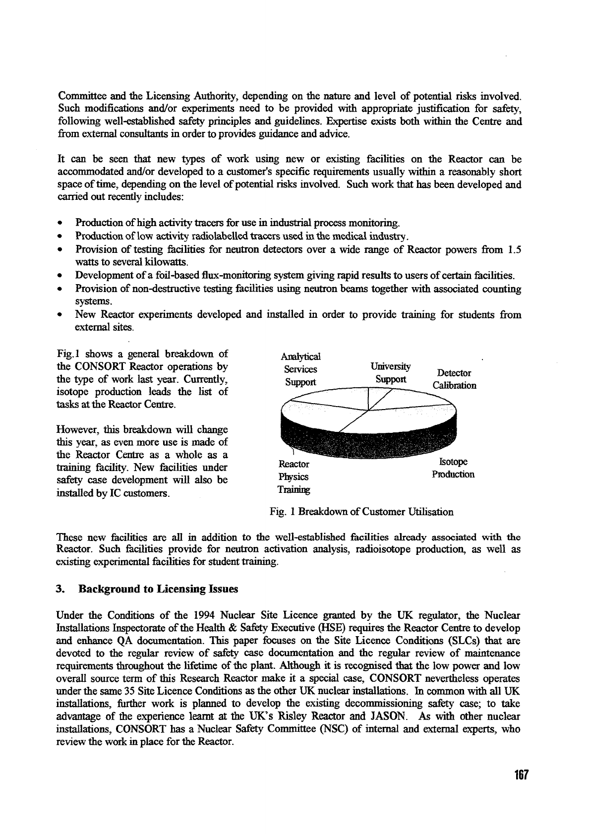
Fig.l shows a general breakdown of
the CONSORT Reactor operations by
the type of work last year. Currently,
isotope production leads the list of
tasks at the Reactor Centre.
However, this breakdown will change
this year, as even more use is made of
the Reactor Centre as a whole as a
training facility. New facilities under
safety case development will also be
installed by IC customers.
Analytical
Services
Support
Univeisity
Support
Detector
Calibration
Reactor
Physics
Training
Isotope
Production
Fig. 1 Breakdown of Customer Utilisation
These new facilities are all in addition to the well-established facilities already associated with the
Reactor. Such facilities provide for neutron activation analysis, radioisotope production, as well as
existing experimental facilities for student training.
3.
Background to Licensing Issues
Under the Conditions of the 1994 Nuclear Site Licence granted by the UK regulator, the Nuclear
Installations Inspectorate of the Health & Safety Executive (HSE) requires the Reactor Centre to develop
and enhance QA documentation. This paper focuses on the Site Licence Conditions (SLCs) that are
devoted to the regular review of safety case documentation and the regular review of maintenance
requirements throughout the lifetime of the plant. Although it is recognised that the low power and low
overall source term of this Research Reactor make it a special case, CONSORT nevertheless operates
under the same 35 Site Licence Conditions as the other UK nuclear installations. In common with all UK
installations, further work is planned to develop the existing decommissioning safety case; to take
advantage of the experience learnt at the UK's Risley Reactor and JASON. As with other nuclear
installations, CONSORT has a Nuclear Safety Committee (NSC) of internal and external experts, who
review the work in place for the Reactor.
167
Operations
to
monitor
the
Reactor systems
for
signs
of
ageing
are
ongoing,
and
have been discussed
previously
[2].
This paper reports
the
progress
of
that programme,
and the
plans
to
development
and
extend
the
existing safety case
4.
The
Safety Report
SLC
15
requires that arrangements
are
made
to
review
the
safety case
at
appropriate intervals.
The
arrangements require review every
10
years;
the
latest review began
in
late
1995, and the
extended report
is
due to be
completed
in May 1999. It is
intended that
the
layout
of the
revised report will follow both
the IAEA Guidelines
[4], and the HSE
guidance provided
to its own
Nuclear Installations Inspectorate
[5,6].
This will update
the
safety case from
its
current deterministic basis
to
take advantage
of
the modem
techniques developed
in
Nuclear Power Plants
and
incorporate probabilistic safety assessment.
In order
to
assess
the
likely behaviour during steady state
and
transient events,
a
hydrodynamic
and
point
kinetics model
has
been constructed using
the
PARET code, which
has
been applied
to the
IAEA standard
Research Reactor
[3].
Firstly,
all
potential faults have been identified
in all
parts
of the
Reactor system.
Event trees have then been constructed
to
enable
the
probabilistic safety assessment
to be
made. This will
be combined with
a
radiological assessment
of
normal operational behaviour
and
behaviour during faults.
Particular emphasis place
on
sensitivity studies where parameters have uncertainties that
are
difficult
to
quantify.
5. Technical Specification
CONSORT
is a 100 kW
light water moderated, reflected/shielded
and
cooled pool-type Reactor, with
the
water cooling being essentially convective.
The
core consists
of 24
fuel elements, each with
a
shroud
of
square cross-section
and
containing
12-16
high-purity aluminium clad plates
of a
UA1 alloy with Highly
Enriched Uranium
(HEU) at
80%.
The
excess core reactivity
is
controlled
by
stainless steel clad cadmium
control rods
(one
safety, plus
two
control).
A
stainless steel
rod is
used
for the
fine adjustments that
are
required
by
feedback changes
due to
changing coolant temperature throughout
a
working
day, as the
Reactor
is
only operated during normal office hours.
The first fuel charge
had an
inventory
of
approximately
3 kg
235
U, providing
an
excess reactivity
of 1%.
The original core
was
supplied
to the
UKAEA Dounreay
/
BNFL Springfields Mark
1
design
in 1964,
with
4
Mark
JE
assemblies (with straight plates) supplied
in 1976, and 5 in 1983 to
raise available
reactivity. Other papers
can
provide more detail about
the
Reactor systems
[1].
6. Refuelling
In common with many other Research Reactor operators,
IC is
exploring
the use of Low
Enriched
Uranium
(LEU) for the
next fuel charge. Because refuelling
is
planned
to
interfere with operations
to
only
a minimal degree,
the
intention
is to
maintain
the
same size core, with
the
same geometry fuel. Work
has
begun
to
analyse
the
fuel design based around
the
uranium silicide route
as
offered
by
UKAEA
Dounreay/BNFL Springfields, which uses enrichments
of ~
20%.
It is
most important
to
maintain
the
flux
levels that
are
currently available
in the
experimental facilities
on
CONSORT.
7.
Control Rod Timing: the Story So Far
In common with Nuclear Power Plants world wide,
the
CONSORT
NSC has
encouraged investigation
of
any trend
in
control blade drop time. Following
a
trip,
the
electromagnetic clutch disengages,
and the
blades drop
on
their stainless steel supporting tapes into channels between extra-spaced fuel.
The
drop
is
168
essentially under gravity, although there is friction from the drive unit drum. A braking system then slows
travel beyond around 60% insertion. The rationale is that distortion in components due to irradiation has
caused incomplete control rod insertion in some PWR designs. During routine monthly testing, variations
had been observed in control rod drop time, although the specification had at no time been violated.
The NSC brief was that no modifications to the actual control rod mechanism would be made. The full
experiment performed has been described previously [2]. A combination of the built-in drop time
measurement facilities, which are used during monthly testing, and are initiated and stopped by micro-
switches for the top and bottom of rod travel, and optical sensors scanning regularly spaced marks on the
control blade tape are used. These together give the rod drop profile can be obtained (for the coarse rods),
although this is subject to some manual data assessment due to data logging with the MCA. Nevertheless,
neither of these methods has indicated any trend in control blade drop times, which remain within
specification.
However, in an effort to gauge the behaviour during the first part of the control blade insertion, plans are
underway to develop a new measurement system that monitors the time between the scram initiation and
50-60%
insertion; the most important part of the shutdown. The ideal situation would be a measurement
of the trip signal initiation to 50% insertion. A method of ascertaining this is under development.
8. Replacement and Upgrades of Reactor Control System.
The Reactor has now been operating safely for almost 33 years. During this time various equipment
upgrades have taken place and routine maintenance programmes have been carried out based on the best
advice available, good engineering practice and previous operational experience. These programmes have
been adapted throughout the lifetime of the Reactor to ensure that up-to-date practices and modern
advances are followed. The Reactor Site Licence formally requires mat safety documentation is
developed to demonstrate the safety of all Reactor operations and that there is a periodic review of all
such safety documentation. These are not new requirements but have lead to an ongoing review of the
nucleonic instrumentation and safety circuits in order to demonstrate that they will continue to perform
reliably with safety maintained, or indeed enhanced, for further operation of the Reactor.
The Reactor control system utilises 108 PO 3000 type relays. These were designed originally for use in.
telephone exchanges and as such operate many times during the working day. In the Reactor control
system they operate on average twice a day. No failures have ever been reported in the operating life of
the Reactor. Data was obtained to give reassurance as to their expected reliability and lifetime. This was
further reinforced by physical testing and maintenance performed in-house. Data has also been obtained
on cable ageing in order to provide reassurance for future operation. Again, in-house testing and checking
of cable integrity was performed in order to reinforce these findings.
There are five independent power monitoring instrumentation channels. Each channel consists of a
module containing several of the following units: power supply, EHT supply, amplifiers, alarm units and
trip units. This instrumentation had been replaced over a period of time in the early 1980s, but is now
ageing and could give rise to potential maintenance problems, as some of the components they use are no
longer obtainable. Complete modules are also not available to buy "off the
shelf',
and it would be
extremely expensive and time consuming to have a suite of new instrumentation built to order by an
outside supplier. As the original circuit diagrams and technical documents for each unit were available, it
was decided to build new units to the original designs that would be updated to utilise modern
components and reflect modern practices and design advances. The new units are built in-house, although
an external consultant provides the updated designs and component schedules. Soak testing of each new
unit prior to installation is also carried out externally to the original test schedules. Units are built, tested
and installed individually so that, over a period of time, the whole instrumentation suite will be replaced.
Old replaced units are then refurbished and kept as spares. The replacement strategy has concentrated on
169
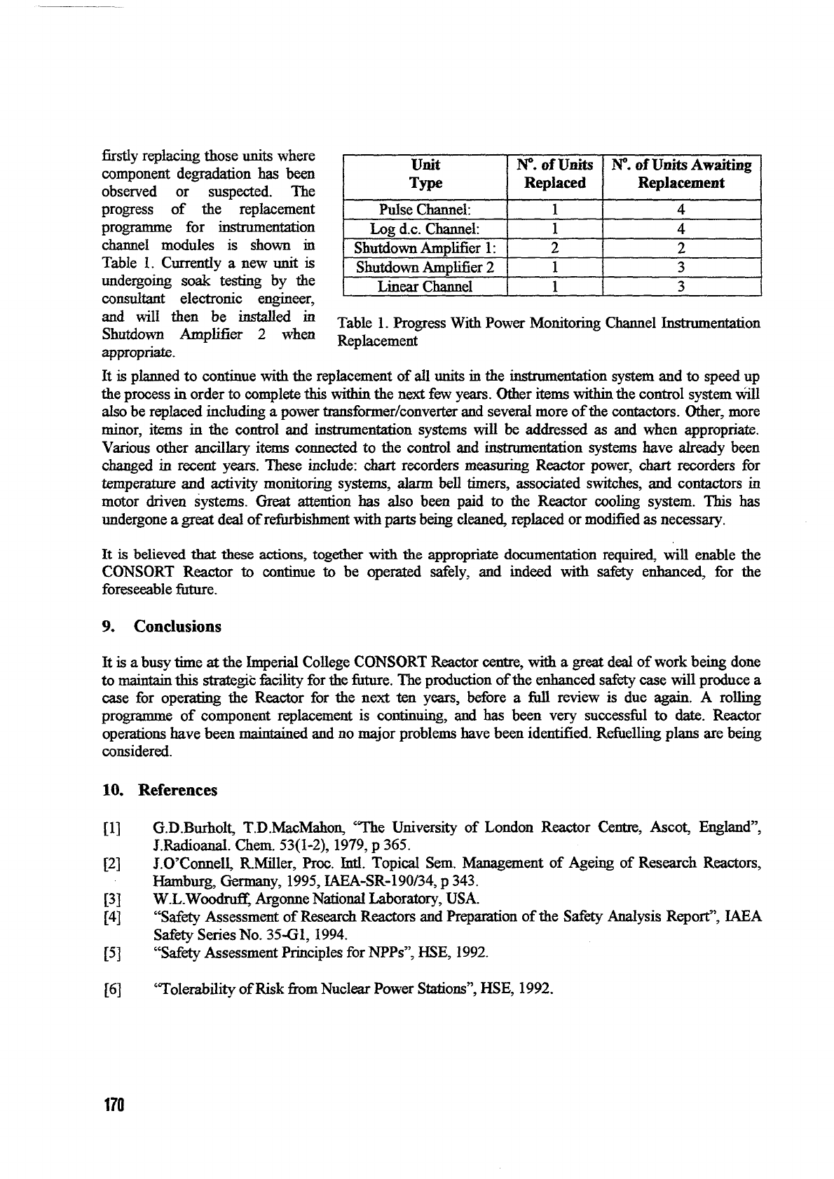
firstly replacing those units where
component degradation has been
observed or suspected. The
progress of the replacement
programme for instrumentation
channel modules is shown in
Table 1. Currently a new unit is
undergoing soak testing by the
consultant electronic engineer,
and will then be installed in
Shutdown Amplifier 2 when
appropriate.
Unit
Type
Pulse Channel:
Log d.c. Channel:
Shutdown Amplifier 1:
Shutdown Amplifier 2
Linear Channel
N°.
of Units
Replaced
1
1
2
1
1
N°.
of Units Awaiting
Replacement
4
4
2
3
3
Table 1. Progress With Power Monitoring Channel Instrumentation
Replacement
It is planned to continue with the replacement of all units in the instrumentation system and to speed up
the process in order to complete this within the next few years. Other items within the control system will
also be replaced including a power transformer/converter and several more of the contactors. Other, more
minor, items in the control and instrumentation systems will be addressed as and when appropriate.
Various other ancillary items connected to the control and instrumentation systems have already been
changed in recent years. These include: chart recorders measuring Reactor power, chart recorders for
temperature and activity monitoring systems, alarm bell timers, associated switches, and contactors in
motor driven systems. Great attention has also been paid to the Reactor cooling system. This has
undergone a great deal of refurbishment with parts being cleaned, replaced or modified as necessary.
It is believed that these actions, together with tiie appropriate documentation required, will enable the
CONSORT Reactor to continue to be operated safely, and indeed with safety enhanced, for the
foreseeable future.
9. Conclusions
It is a busy time at the Imperial College CONSORT Reactor centre, with a great deal of work being done
to maintain this strategic facility for the future. The production of the enhanced safety case will produce a
case for operating the Reactor for the next ten years, before a full review is due again. A rolling
programme of component replacement is continuing, and has been very successful to date. Reactor
operations have been maintained and no major problems have been identified. Refuelling plans are being
considered.
10.
References
[1] G.D.Burholt, T.D.MacMahon, "The University of London Reactor Centre, Ascot, England",
J.Radioanal. Chem. 53(1-2), 1979, p 365.
[2] J.O'Connell, R.Miller, Proc. Intl. Topical Sem. Management of Ageing of Research Reactors,
Hamburg, Germany, 1995, IAEA-SR-190/34, p 343.
[3] W-L-WoodrufF, Argonne National Laboratory, USA.
[4] "Safety Assessment of Research Reactors and Preparation of the Safety Analysis Report", IAEA
Safety Series No. 35-G1,1994.
[5] "Safety Assessment Principles for NPPs", HSE, 1992.
[6] "Tolerability of Risk from Nuclear Power Stations", HSE, 1992.
170
